background image

HZ42ST Regency Horizon

TM

 Gas Fireplace

4

INST

ALLA

TION

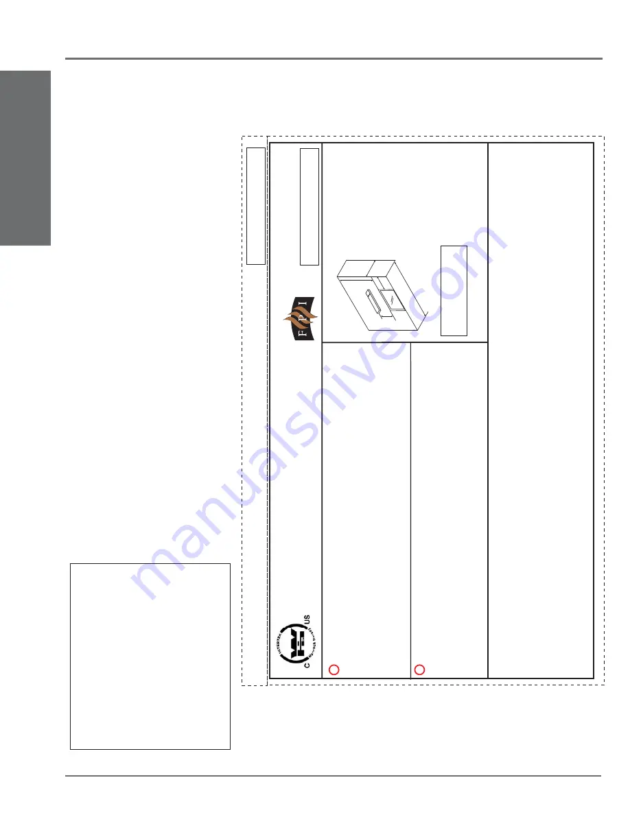
SAFETY LABEL

This is a copy of the label that accompanies 
each HZ42 ST-NG and HZ42 ST-LP Direct Vent 
Gas Fireplace. We have printed a copy of the 
contents here for your review. 

NOTE:

 Regency

®

 units are constantly being 

improved. Check the label on the unit and if 
there is a difference, the label on the unit is the 
correct one.

COPY

 OF SAFETY

 DECAL

For the State of Massachusetts, installation 
and repair must be done by a plumber or 
gasfi tter licensed in the Commonwealth of 
Massachusetts.

For the State of Massachusetts, fl exible 
connectors shall not exceed 36 inches in 
length.

For the State of Massachusetts, the appli-
ances individual manual shut-off must be a 
t-handle type valve.

The State of Massachusetts requires the 
installation of a carbon monoxide alarm in 
accordance with NFPA 720 and a CO alarm 
with battery back up in the same room where 
the gas appliance is installed.

DO

NOT

REMOVE

THIS

LABEL

/

N

E

P

AS

ENLEVER

CETTE

ÉTIQUETTE

350

350

DOOR

SEAL:

Please

check

that

the

door

is

properly

sealed

FPI

Fireplace

Products

International

Ltd.

Delta,

BC,

Canada

Minimum

Clearances

to

Combustibles

/

Degagement

Minimum

De

Materiaux

Combustibles

Serial

No./

No

de

serie

918-809a

MA

Y

B

E

INST

ALLED

IN

MANUF

ACTURED

(MOBILE)

HOMES

AFTER

FIRST

SALE

.

Listed:

Certified

for/Certifi

e

pour:

T

ested

to:

WN

#

16380

VENTED

GAS

FIREPLACE

HEA

TER

/

CANADA

and

U.S.A.

FOYER

AU

GAZ

À

É

V

ACUA

TION

é

CAN/CGA-2.17-M91,ANSI

Z21.88a-2007/CSA

2.33a-2007

Electrical

supply

/

Électrique

1

15V

AC,

1.13

A,

60Hz.

NOT

FOR

USE

WITH

SOLID

FUELS.

/

NE

P

A

S

UTILISER

A

VEC

DU

COMBUSTIBLE

SOLIDE.

Made

in

Canada/

Fabrique

au

Canada

Duplicate

S/N

(

See

Instruction

Manual

for

detailed

instructions)

ÉÉ

é

QUIP

A

L'UISINE

POUR

G

AZ

PROP

ANE

CONCU

POUR

ETRE

POELE:

Mod

le

HZ42

ST

PROP

ANE

GAS:

Model

HZ42ST

-LP

Minimum

supply

pressure

Manifold

pressure

high

Manifold

pressure

low

Orifice

size

Minimum

input

Maximum

input

Altitude

NA

TURAL

GAS:

Model

HZ42ST

-NG

APP

AREIL

FONCTIONNANT

AU

NA

TURAL

GAS

CONCU

POUR

ETRE

POELE:

Mod

le

HZ42

ST

Pression

d'allimentation

minimum

Pression

à

la

tubulure

d

'

c

happement

lev

e

Pression

à

la

tubulure

d

'

c

happement

basse

Grandeur

de

l'injecteur

D

bit

minimum

selon

D

bit

maximum

s

elon

l'altitude

Calorifique

Calorifique

é

éé

é

é

é

é

5.0"

(1.25

kPa)

3.5"

(0.87

kPa)

1.6"

(0.40

kPa

)

#4

0

D

M

S

0-4500

ft/pi

(0-1372

m)

WC/C.E.

WC/C.E.

WC/C.E.

17,500

Btu/h

(5.13

kW)

26,000

Btu/h

(7.62

kW)

Pression

d'allimentation

minimum

Pression

à

la

tubulure

d

'

c

happement

lev

e

Pression

à

la

tubulure

d

'

c

happement

basse

Grandeur

de

l'injecteur

D

bit

minimum

selon

D

bit

maximum

s

elon

l'altitude

Calorifique

Calorifique

éé

é

é

é

é

12“

W

C

(2.98

kpa)

WC/C.E.

WC/C.E.

19,500

Btu/h

(5.71

kW)

24,500

Btu/h

(7.18

kW)

10"

(2..49

kPa)

6.4"

(1.60

kPa

)

#5

3

D

M

S

0-4500

ft/pi

(0-1372

m)

Minimum

supply

pressure

Manifold

pressure

high

Manifold

pressure

low

Orifice

size

Minimum

input

Maximum

input

Altitude

D

E

F

A

B

C

Side

W

alls

A

8

(203mm)

B

2

2”

(559mm)

C

13"

(330mm)

D

1

3”

(330mm)

E

84"

(2133mm)

F

36"

(914mm)

Ceiling

Min.

Mantel

Height

Max.

Mantel

Depth

Alcove

W

idth

Alcove

Depth

This

appliance

must

be

installed

in

accordance

with

local

codes,

if

any;

if

none,

follow

the

National

Fuel

Gas

Code,

ANSI

Z223.1,

or

Natural

Gas

and

Prop

ane

Installation

Code,

CSA

B149.1.

This

appliance

must

be

installed

in

accordance

with

the

Standard

CAN/CSA

Z240

MH,

Mobile

Housing,

in

Canada,

or

with

the

Manufactured

Home

Constructi

on

and

Safety

Standard,

T

itle

24

CFR,

Part

3280,

in

the

United

States,

or

when

such

a

standard

is

not

applicable,

ANSI/NCSBCS

A225.1/NFP

A

501A,

Manufactured

Home

Installations

Standard

or

ANSI

A1

19.2

ou

NFP

A

501C

Standard

for

Recreational

V

ehicles

This

appliance

is

only

for

use

with

the

type

of

gas

indicated

on

the

rating

plate

and

may

be

installed

in

an

aftermarket,

permanently

located,

manufactu

red

(mobile)

home

where

not

prohibited

by

local

codes.

See

owner's

manual

for

details.

Installer

l'appareil

selon

les

codes

ou

règlements

locaux,

ou,

en

l'absence

de

tels

règlements,

selon

les

codes

d'installation

ANSI

Z223.1,

Nationa

lFuel

Gas

Code

ou

CSA-B149.1

en

vigueur

.

Installer

l'appareil

selon

la

norme

CAN/CSA-Z240,

Série

MM,

Maison

mobiles

ou

CAN/CSA-Z240

VC,

Véhicules

de

camping,

ou

la

norme

24

CFR

Part

3280,

Man

ufactured

Home

Construction

and

Safety

Standard.

Si

ces

normes

ne

sont

pas

pertinentes,

utilisez

la

norme

ANSI/NCSBCS

A225.1/NFP

A

501A,

Manufactured

Home

Installations

Standard,

ou

ANSI

A1

19.2

ou

NFP

A

501C

Standard

for

Recreational

V

ehicles.

This

vented

gas

fireplace

heater

is

not

for

use

with

air

filters.

Ne

pas

utiliser

de

filtre

à

air

avec

ce

foyer

au

gaz

à

évacuation.

FOR

USE

WITH

GLASS

DOORS

CERTIFIED

WITH

THE

APPLIANCE

ONL

Y

Cet

appareil

doit

être

utilize

uniquement

avec

le

type

de

gaz

indiqué

sur

la

plaque

signalétique.

Cet

appareil

peut

être

installé

dans

une

maison

préfa

briquée

ou

mobile

(É.-U.

seulement)

installée

à

demeure

si

les

règlements

locaux

le

permettent.

V

oir

la

notice

de

l'utilisateur

pour

plus

de

renseignements.

Cet

appareil

ne

peut

pas

être

utilisé

avec

d'autres

gaz

sauf

si

une

trousse

de

conversion

certifiée

est

fournie.

POUR

UTILISA

TION

UNIQUEMENT

A

VEC

LES

PORTES

EN

VERRE

CERTIFIÉES

A

VEC

L'APP

AREIL

Summary of Contents for Horizon HZ42ST

Page 1: ... any electrical switch do not use any phone in your building Immediately call your gas supplier from a neighbour s phone Follow the gas supplier s instructions If you cannot reach your gas supplier call the fire department FPI FIREPLACE PRODUCTS INTERNATIONAL LTD 6988 Venture St Delta BC Canada V4G 1H4 918 808 Regency Horizon HZ42ST Gas Fireplace 12 24 09 Owners Installation Manual www regency fir...

Page 2: ...EVER WILL CAUSE BURNS GLASS UNTIL COOLED ALLOW CHILDREN TO TOUCH GLASS CHILDREN AND ADULTS SHOULD BE ALERTED TO THE HAZARDS OF HIGH SURFACE TEMPERATURES ESPECIALLY THE FIREPLACE GLASS AND SHOULD STAYAWAYTOAVOIDBURNSORCLOTHINGIGNITION ...

Page 3: ...Safety Standard Title 24 CFR Part 3280 or the current Standard of Fire Safety Criteria for Manufactured Home Installations Sites and Communities ANSI NFPA 501A and with CAN CSA Z240 MH Mobile Home Standard in Canada This appliance installation must comply with the manufacturer s installation instructions and local codes if any In the absence of local codes follow the current National Fuel Gas Code...

Page 4: ...ermination 27 Unit Installation with Horizontal Termination 28 Unit Installation with Vertical Termination 29 High Elevation 30 Gas Line Installation 30 Pilot Adjustment 30 Gas Pipe Pressure Testing 30 S I T Valve Description 30 Aeration Adjustment 31 Wiring Diagram 31 Optional Accent Lighting Wiring Diagram 31 Optional Wall Thermostat 32 Optional Remote Control 32 GT GTM Remote Features 32 Wall S...

Page 5: ...ent lev e Pression à la tubulure d chappement basse Grandeur de l injecteur D bit minimum selon D bit maximum selon l altitude Calorifique Calorifique é é é é é é 12 WC 2 98 kpa WC C E WC C E 19 500 Btu h 5 71 kW 24 500 Btu h 7 18 kW 10 2 49kPa 6 4 1 60kPa 53 DMS 0 4500 ft pi 0 1372 m Minimum supply pressure Manifold pressure high Manifold pressure low Orifice size Minimum input Maximum input Alti...

Page 6: ...de directly in line with the exhaust vent terminal for the horizontally vented gas fueled heating appliance or equipment The sign shall read in print size no less than one half 1 2 inch in size GAS VENT DIRECTLY BELOW KEEP CLEAR OF ALL OBSTRUCTIONS 4 INSPECTION The state or local gas inspector of the side wall horizontally vented gas fueled equipment shall not approve the installation unless upon ...

Page 7: ...6 INSTALLATION DIMENSIONS UNIT DIMENSIONS 18 7 8 479mm 15 381mm 36 1 2 927mm 12 7 8 327mm 1 1 2 38mm 36 914mm 48 3 4 1238mm 30 13 16 783mm 41 3 16 1046mm 3 76mm 1 1 2 38mm 48 11 16 1237mm 23 5 8 600mm 28 5 8 727mm 12 305mm 13mm 21 5 8 549mm ...

Page 8: ...LSHOULDNOTBEPLACED ON OR NEAR THE APPLIANCE INSTALLATION AND REPAIR SHOULD BE DONE BY AN AUTHORIZED SERVICE PERSON THE APPLIANCE SHOULD BE INSPECTED BEFORE USE AND AT LEAST ANNUALLY BY A PROFESSIONAL SERVICE PERSON MORE FREQUENT CLEANING MAY BE REQUIRED DUE TO EXCESSIVE LINT FROM CARPETING BEDDING MATERIAL ETC IT IS IMPERATIVE THAT CONTROL COMPARTMENTS BURNERS AND CIRCULATING AIR PASSAGEWAYS OF TH...

Page 9: ...l switch supplied with the manual package Use of a decor switch causes higher resistance which is a problem on gas fireplaces 12 Final check Before leaving this unit with the customer the installer must ensure that the appliance is firing correctly and operation fully explained to customer LOCATING YOUR GAS FIREPLACE 1 When selecting a location for your fireplace ensure that the clearances are met...

Page 10: ...lose to Ceiling NON COMBUSTIBLE REQUIREMENTS Flue Clearances to Combustibles Horizontal Top 3 Horiztonal Side 2 Horiztonal Bottom 2 Vertical 2 Passing through wall floor ceiling when firestop is used 1 1 2 F B E D A Installed Close to Floor G Clearance Dimension Measured From A Mantel Height min 13 330mm Top of Fireplace Opening B Sidewall on one side 8 203mm Side of Fireplace Opening C Ceiling ro...

Page 11: ... 16 5 419mm 13 5 343mm 16 5 419mm 13 5 343mm 9 1 2 241mm 9 1 2 241mm 13 5 343mm 16 5 419mm 2 0 12 6 4 8 10 Top of Fireplace Opening 0 14 To Unit Base 1 25mm 22 13 25 3 4 10 20 26 Combustible Material 2 0 12 6 4 8 10 Top of Fireplace Opening Standoff Metal Stud On Edge 0 14 Non combustible Facing 1 25mm 13 10 20 26 2 0 12 6 4 8 10 Top of Fireplace Opening 12 305mm 0 14 To Unit Base 1 25mm 21 1 2 13...

Page 12: ...extender on top of the deflector with 2 screws slide the extender until it touches the outside wall tighten screws to secure Extender can be adjusted to max 15 1 2 Nailing Strips Standoff UNIT ASSEMBLY PRIOR TO INSTALLATION TheStandoffsandNailingStripsmustbecorrectlypositionedandattached to the firebox before unit is slid into position STANDOFF ASSEMBLY The side top and rear standoffs are shipped ...

Page 13: ...diagram below The faceplate will not be able to be mounted if the finished material is beyond 1 1 2 FRAMING FINISHING 1 Frame in the enclosure for the unit with framing material IMPORTANT Vertical studs and the header must be metal Note Depending on the material used for finishing the nailing strips must be set accordingly so that the finished material is always at the 1 1 2 edge of the flange 4 I...

Page 14: ...as Connection Opening Height 2 51mm Framing depth measurement is noted with nailing strips top sides set as far forward on the firebox as possible The nailing strips can be adjusted back up to 1 on both sides to allow for varying thicknesses in non combustible material and wall finishes Finished material thickness includes non combustible material tile slate etc example framing 13 if 1 thick finis...

Page 15: ...gements diagrams refer to the following instructions 1 Remove the glass door 2 Remove the screws that hold the vent restrictor plate in place 3 Adjust the vent restrictor plate to the required vent restrictor position as per the diagrams shown 4 Once the vent restrictor plate is in the required position secure with screws VENT RESTRICTOR POSITION 3 4 1 1 4 2 1 2 3 SET 0 FACTORY SET THIS HOLE SETS ...

Page 16: ...bove meter regulator assembly 36 90cm a J Clearance to service regulator vent outlet 36 90cm K Clearance to non mechanical air supply inlet to building or the combustion air inlet to any other appliance 12 30cm 9 23cm L Clearance to a mechanical air supply inlet 3 91cm above if within 10 3m horizontally 72 1 8m 36 90cm b M Clearance above paved sidewalk or a paved driveway located on public proper...

Page 17: ...A N A Adjustable Length 3 10 Galvanized N A N A N A 4DAL N A TC 4DLT Adjustable Length 3 10 Black N A N A N A 4DALB N A TC 4DLTB Adjustable Length 7 Galvanized N A N A 4D7A N A N A N A Adjustable Length 7 Black N A N A 4D7AB N A N A N A Extension Pipe 8 1 2 Galvanized 46DVA 08A N A N A N A N A N A Extension Pipe 8 1 2 Black 46DVA 08AB N A N A N A N A N A Adjustable Length 12 Galvanized N A N A 4D1...

Page 18: ...on 36 46DVA HC N A N A N A N A TM 4ST36 Basic Horizontal Termination Kit A Disc 4DT HKA 4DHTK2 4DHTKA SV SHK N A Horizontal Termination Kit B 46DVA KHA Changed Components 4DT HKB 4DHTK1 4DHTKB SV HK N A Vertical Termination Kit Disc 4DT VKC 4DHTK 4DHTK SV FK N A FPI 946 506 P Vent Guard Optional for AstroCap 946 205 Vinyl Siding Shield for Riser Vent Terminal 510 994 Rigid Pipe Adaptor Must use wi...

Page 19: ...inations of vertical runs with horizontal terminations using one 45º and one 90º two 45o elbows equal to one 90o for direct horizontal runs with horizontal termination use only one 45º elbow Note Must use optional rigid pipe adapter Part 510 994 when using Rigid Pipe Venting Systems VENT RESTRICTOR SETTING Vent restrictor factory set no adjustment required unless otherwise indicated Refer to the V...

Page 20: ... 6 5 8 flexible outer liner Kit length 2 4 flexible inner liner Kit length 3 spring spacers 4 thimble 5 AstroCap termination cap 6 screws 7 tube of Mill Pac 8 plated screws 9 S S screws 8 x 1 1 2 drill point 946 515 4 Feet 946 516 10 Feet HORIZONTAL TERMINATIONS FLEX VENT 4 X 6 5 8 These venting systems in combination with the HZ42 Direct Vent Gas Fireplace has been tested and listed as a direct v...

Page 21: ... using Rigid Vent other than Simpson Dura Vent 3 screws must be used to secure rigid pipe to adaptor This product has been evaluated by Intertek for using a Rigid Pipe Adaptor in conjunction withDuraventDirect Vent SelkirkDirect Temp AmeriVentDirect ICCExcel MetaFabventing and Security Secure Vent systems Use of these systems with the Rigid Pipe adaptor is deemed acceptable and does not affect the...

Page 22: ...ax 7 Min 7 Max E 5 Max 9 Min 8 Max F 6 Max 11 Min 9 Max Restrictor Position Set 0 factory setting Restrictor Position Set 0 factory setting HORIZONTAL TERMINATIONS RIGID PIPE 4 X 6 5 8 The diagrams below shows examples of horizontal termination arrangements using one two or three 90o elbows two 45o elbows equal one 90o elbow 1 A maximum of three 90o elbows are permitted not including the starting ...

Page 23: ...B 3 Min 2 Max 4 Min 5 Max C 4 Min 3 Max 6 Min 6 Max D 5 Min 4 Max 8 Min 7 Max E 6 Min 5 Max 10 Min 8 Max F 7 Min 6 Max 12 Min 9 Max Restrictor Position Set 0 factory setting Horizontal Venting with Two 2 90o Elbows One 90o elbow Two 45o elbows Option H V H H1 With these options maximum total pipe length is 30 feet with minimum of 8 feet total verticalandmaximum8 feet total horizontal Please note m...

Page 24: ...restrictor from Set 0 factory setting to Set 1 to Set 2 or Set 3 if required Note Must use optional flue adaptor when using Rigid Pipe Part 510 994 VENTING ARRANGEMENT FOR VERTICAL TERMINATIONS The shaded area in the diagram shows all allowable combinations of straight vertical and offset to vertical terminations using one 90o elbows with Rigid Pipe Venting Systems for Natural Gas Two 45o elbows e...

Page 25: ...impson Dura Vent Direct Vent American Metal Products Ameri Vent Direct Vent Security Secure Vent ICC Excel Selkirk Direct Temp AstroCapTM is a proprietary trademark of FPI Fireplace Products International Ltd Dura Vent and Direct Vent are registered and or proprietary trademarks of Simpson Dura Vent Co Inc Roof Pitch Minimum Vent Height Feet Meters flat to 7 12 2 0 61 over 7 12 to 8 12 2 0 61 over...

Page 26: ...ngth is 30 feet with minimum of 6 feet total vertical and maximum 6 feet total horizontal Please note minimum 1 foot between 90o elbows is required A 2 Max 2 Min B 3 Max 3 Min C 4 Max 4 Min D 5 Max 5 Min E 6 Max 6 Min Restrictor Position Set 0 factory setting Restrictor Position Set 0 factory setting VERTICAL TERMINATIONS RIGID PIPE 4 X 6 5 8 Two 45o elbows equal to one 90o elbow Maximum of four 4...

Page 27: ... these options max total pipe length is 30 feet with min of 11 feet total vertical and max 7 feet total horizontal Please note min 1 foot between 90o elbows is required Option V H H1 V V1 A 2 Min 3 Max 4 Min B 3 Min 4 Max 6 Min C 4 Min 5 Max 7 Min D 5 Min 6 Max 8 Min E 6 Min 7 Max 9 Min F 7 Min 8 Max 10 Min With these options max total pipe length is 30 feet with min of 10 feet total vertical and ...

Page 28: ...laronlywiththe3suppliedscrews drilling pilot holes will make this easier 4 Levelthefireplaceandfastenittotheframing using nails or screws through the top and side nailing strips Diagram 1 Note For best results and optimum performance with each approved venting system it is highly recommended to apply Mill Pac sealant supplied to every inner pipe connection Failuretodosomayresult in drafting or per...

Page 29: ...nd can be adjusted for 2 x 4 or 2 x 6 walls 5 Slip the assembled liner and termination assembly through the thimble making sure the termination cap faces up there are markings on the cap that show which wayis up This will position the termination cap with proper down slope for draining water Fasten the cap to the outer wall with the 4 supplied screws 6 Pull the centre inner and outer flex liner ou...

Page 30: ...ections are in the fully twist locked position and sealed 5 Cut a hole in the roof centered on the small drilled hole placed in the roof in Step 2 The hole should be of sufficient size to meet the minimum requirements for clearance to combustibles of 1 1 2 Slip the flashing under the shingles shingles should overlap half the flashing as per Diagram 3 6 Continue to assemble pipe lengths Note If an ...

Page 31: ...r the current National Fuel Gas Code ANSI Z223 1 When using copper or flex connectors use only approved fittings Always provide a union so that gas lines can be easily disconnected for servicing Flare nuts for copper lines and flex connectors are usually considered to meet this requirement NOTE Ashutoff dante valve should be sup pliedinorneartheunit orasperlocalcodes for ease of servicing this app...

Page 32: ...re yellow flame Minimum Air Shutter Opening NG Fully Closed LP 3 16 CAUTION Label all wires prior to disconnection whenservicingcontrols Wiringerrorscancause improper and dangerous operation Caution Ensure that the wires do not touch any hot surfaces and are away from sharp edges Note Any damage due to carboning resulting from improperly setting the aeration controls is NOT covered under warranty ...

Page 33: ...0V wire Optional REMOTE CONTROL UsetheRegency RemoteControlKit approved for this unit Use of other systems may void your warranty The remote control kit comes with a hand held transmitter a receiver and a wall mounting plate 1 Choose a convenient location on the wall to install the receiver and the receptacle box protection from extreme heat is very important Run wires from the fireplace to that l...

Page 34: ...time Claims for damage after installation will not receive consideration Black Enamel panels must be inspected for scratches and dimples prior to installation All claims to be recorded at this time Claims for damage after installation will not receive consideration To protect the finish during installation and handling cotton gloves MUST be worn at all times while handling the panels even when Use...

Page 35: ...low Plug Wiring Light Diffuser Amber Glass 7 Remove bottom cover Bottom cover 10 Feed the plug wiring through the opening in the middle of the firebox secure light assembly mounting plate with 4 screws use screws from cover plate HZ42ST Accent Light Assembly Kit 586 959 1 910 814 Plug wiring gasket 4 910 997 Halogen Bulb 4 940 363 Amber Glass 1 Light Assembly Includes gaskets x 4 1 918 829 Instruc...

Page 36: ...ket over the inside perimeter of the light diffuser box 15 From outside the firebox Install light assembly box and gasket into opening created from the removal of the cover plates open end up as shown below 16 Secure the light diffuser in place with the 4 screws set aside from the cover plates 17 Slide amber glass into light diffuser to reinstall 18 Install bulb into socket end of assembly Note Oi...

Page 37: ...e socket end of the diffuser and separate the 2 parts as shown below 3 Pull out light diffuser BULB REPLACEMENT 1 Slide out bottom faceplate panel see step 3 from previous page 2 Remove 4 screws securing light diffuser mounting plate 6 Reverse steps 3 through 1 5 Replace bulb Note Oils from hands will shorten the life of the bulbs do not handle bulbs with bare hands 21 Repeat steps 12 20 to instal...

Page 38: ...spa stones E33S 1 Bag 1 package 70 spa stones NOTE 1 package contains 70 stones Recommended use only 50 of the 70 ceramic stones on the P33S burner Evenly spread the supplied Glass Crystals or optional Ceramic Spa Stones over the burner Ensure the crystals or stones do not overlap too much as this will effect the flame pattern IMPORTANT NOTES When installing use either the supplied Glass Crystals ...

Page 39: ...s Crystals or optional Ceramic Spa Stones NOTE Only the supplied and approved pebbles crystals are to be used Use of any other type of pebbles or material can create a danger and will void warranty Glass Crystals shown surrounding the Burner Firebox Packages Unit Glass Crystals Pebbles HZ54 6 Bags 2 packages 6 x bags pebbles HZ42 5 Bags 2 packages 6 x bags pebbles HZ42 ST 5 Bags 1 package 6 x bags...

Page 40: ...lass door simply hook the top door flange onto the top of the unit and swing the door towards the unit Diagram 1 Note Be careful that the glass gasket does not roll up there must be a gap between the gasket and the door lip to ensure that the door sits securely on the unit See Diagram 2 2 With the door in proper position secure with 3 screws in locations shown in Diagram 3 Diagram 2 Diagram 3 Diag...

Page 41: ...lls on the unit with 2 slides These slides are located in the bottom of the unit already installed within the outer slide The inner slides need to be removed to install them on the brackets 6 Position the faceplate bracket and slide under the mounting plate The mounting plate is located on the inside lower edge of the faceplate panel Glass Door Faceplate Inner Slide Backside of Faceplate Panel Mou...

Page 42: ... slides attached to the lower faceplate panel guide the lower faceplate panel into the outer slides located in the bottom part of the unit See inset Push in until flush with upper faceplate 7 Attach bracket and slide slide facing in to the bottom faceplate panel with 4 screws Note Screw locations and brackets differ between HZ42 and HZ42 ST units Identify left and right brackets before installatio...

Page 43: ...ew fires a white film may develop on the glass front as part of the curing process The glass should be cleaned after the unit has cooled down or the film will bake on and become very difficult to remove Use a non abrasive cleanerandDONOTATTEMPTTOCLEAN THE GLASS WHILE IT IS HOT TheFIRSTFIREinyourheaterispartofthepaint curing process To ensure the paint is properly cured it is recommendedyou burnyou...

Page 44: ...nob Never use tools If the knob will not push in or turn by hand don t try to repair it call a qualified service technician Forced or attempted repair may result in a fire or explosion D Do not use this appliance if any part has been under water Immediately call a qualified service technician to inspect the appliance and to replace any part of the control system and any gas control which has been ...

Page 45: ...e Cap and shine a flashlight down the Vent Remove any bird nests or other foreign material 3 Check for evidences of excessive condensation suchaswaterdropletsforming in the inner liner and subsequently dripping outthejoints Continuouscondensationcan cause corrosion of caps pipe and fittings It may be caused by having excessive lateral runs too many elbows and exterior portions of the system being ...

Page 46: ...as shown below 3 RemovethebatterycoverfromtheDCSpark Box DC Spark Box mounting plate partially removed Generator Wires Diagram 1 DC Spark Box mounting plate partially removed 4 Remove the AA battery and replace with a new one 5 Reverse steps 3 to 1 Spark Electrode Wire DC Spark Box Ground Wire 5 Remove the 2 screws that secure the DC spark box to the mounting plate 6 Replace DC spark box reconnect...

Page 47: ...om cover by lifting up and out 6 Remove burner by removing 2 screws 7 Slide burner away from the pilot and lift out 4 Remove the glass door a Remove the 3 screws shown below at the bottom of the glass door b Swing the door out 45o from the bottom and lift up and out Faceplate Glass Door Aerial View of the burner shown 9 Disconnect the DC Sparker leads at the valve ON OFF Connector Wires 8 Disconne...

Page 48: ...11 Disconnect the spark electrode wire from the DC spark box shown in the image below 12 Disconnect the 2 DC spark generator wires from the DC Spark box located on the left side of the DC spark box as shown below Generator Wires Spark Electrode Wire 13 Remove the valve assembly by undoing 12 screws 14 Partially lift out valve tray 15 Disconnect the inlet gas line and remove the valve assembly 16 R...

Page 49: ... 576 P Valve Assembly LP 6 910 568 Valve 820 7 910 008 Pilot Assembly NG 910 009 Pilot Assembly LP 8 904 593 Orifice 40 NG 904 345 Orifice 53 LP 9 948 484 Slide Hinge 904 658 Inlet Gas Flex Line SS 430 011 Flue Collar Gasket 586 047F Relief plate door 586 048 Plate Relief Gasket 586 089 Valve Tray Gasket 430 011 Inner Flue Collar Gasket 586 017F Flue Restrictor Plate 586 016F Gas line cover 586 06...

Page 50: ... Bronze 586 917 Faceplate Brushed Stainless 946 671 Cobalt Blue Glass Crystals 946 672 Natural River Pebbles 946 673 White River Pebbles 946 674 Ceramic Spa Stones 946 680 GT Proflame Remote Control 946 681 GTM Proflame Remote Control 946 683 GTM NG Modulator 946 684 GTM LP Modulator 910 574 GTM Wire Harness 910 576 Cover Wall Mount white 910 572 Receiver GTM SIT w Batt Cover PARTS LIST ACCESSORIE...

Page 51: ...HZ42ST Regency HorizonTM Gas Fireplace 50 NOTES ...

Page 52: ...t be returned to the distributor or agent Transportation Prepaid if requested Porcelain Enamel Absolute perfection is either guaranteed nor commercially possible Any chips must be reported and inspected by an authorized dealer within three days of installation Reported damage after this time will be subject to rejection It is the general practice of Regency to charge for larger higher priced repla...

Page 53: ...___________________________________________ Printed in Canada Regency Horizon is a trademark of FPI Fireplace Products International Ltd Register your Regency online at http www regency fire com Copyright 2009 FPI Fireplace Products International Ltd All rights reserved Regency fireplaces are designed with reliability and simplicity in mind In addition our internal Quality Assurance Team carefully...

Reviews: