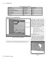
WARNING
•
Always maintain required clearances (air spaces) to nearby combustibles to prevent a fire hazard. Do not fill air spaces with insulation. Unless
stated otherwise, clearances on horizontal vent sections are 2” (51mm) to combustible materials. Clearances to vertical vent sections are 1” (25mm)
to combustible clearances.
•
The fireplace and vent system must be vented directly to the outside of the building. Each direct vent fireplace must use its own separate vent
system. Common vent systems are prohibited.
•
The flow of combustion and ventilation air not be obstructed.
HORIZONTAL INSTALLATION:
Step
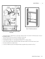
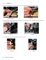
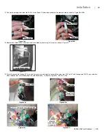
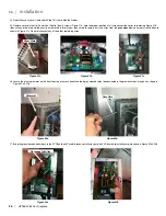
1. Set the fireplace in its desired location. Check to determine if wall studs or roof rafters are in the way when the venting system is attached. If this is
the case, you may want to adjust the location of the appliance.
Step 2.
Direct Vent pipe and fittings are designed with special twist-lock connections. Assemble the desired combination of pipe and elbows to the appliance.
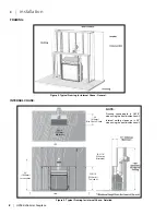
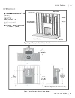
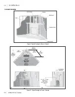
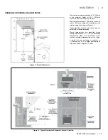
See the sections on
t
yPIcal
f
ramIng
- I
nternal
c
hase
, e
xternal
c
hase
or
c
orner
I
nstallatIon
for some of the possible vent pathway options. All
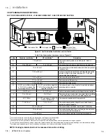
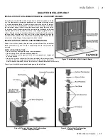
installations must fall within the Allowable Vent Configurations shown in Figure 20.
Notes:
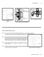
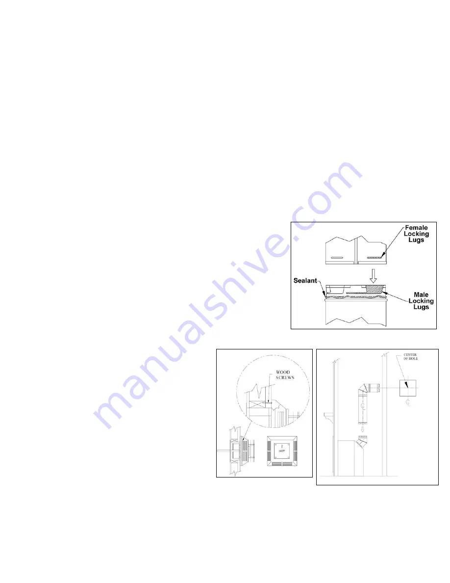
(1) Twist-lock procedure: Four (4) indentations, located on the female ends of pipes and fittings, are designed to slide straight onto the male ends of adjacent
pipes and fittings, by orienting the four pipe indentations so they match and slide into the four (4) entry slots on the male ends. Push the pipe sections
completely together, then twist-lock one section clockwise approximately one-quarter turn, until the two (2) sections are fully locked.
(2) Horizontal runs of vent must be supported every 3 feet (915mm). Wall Straps are available for
this purpose.
(3) Sealant is only necessary on the outer tube of the GS Pipe. Run a
1.25
inch (3mm) wide bead of
sealant around the male end of the outer sleeve, as shown in Figure 34, and twist-lock the pipes
or fittings together.
Step 3.
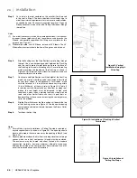
With the adaptor and pipe attached to the fireplace, slide the fireplace into its correct
location, and mark the wall for a square hole of the appropriate size. Use 11”x11”
(280x280mm) square hole for 8” x 5” pipe. The center of the square hole should line up
with the centerline of the horizontal pipe, as shown in Figure 35. Cut and frame the square
hole in the exterior wall where the vent will be terminated. If the wall being penetrated is
constructed of non-combustible material, i.e. masonry block or concrete, a hole with zero
clearance to the pipe is acceptable.
Notes:
(1) Any horizontal run of vent must have a ¼ inch (6mm) rise for every 1 foot (305mm) of run towards
the termination. Never allow the vent to run downward. This could cause high temperatures and
may present the possibility of a fire.
(2) The location of the horizontal vent termination on an exterior wall
must meet all local and national building codes, and must not be
easily blocked or obstructed. Termination clearances must comply
with the
v
ent
t
ermInatIon
r
estrIctIons
section.
Step 4.
For a Square Horizontal Vent Termination, place the vent cap
in the center of the square hole and attach to the exterior
wall with the four wood screws provided (refer to Figure 36).
Before attaching the Vent Termination to the exterior wall, run
a bead of non-hardening sealant around its outside edges, so
as to make a seal between it and the wall. If you are using a
Round Horizontal Vent Termination, place an exterior Wall
Firestop over the square hole. Run a bead of non-hardening
sealant around the edges of the Wall Firestop, and attach the
Wall Firestop to the wall with the four wood screws provided.
The arrow on the vent cap should be pointing up. Ensure that
proper clearances to combustible materials are maintained.
Notes:
(1) The four (4) wood screws provided should be replaced with
appropriate fasteners for stucco, brick, concrete, or other types
o f
sidings.
(2) For buildings with vinyl siding, a Vinyl Siding Standoff should be installed between the vent cap and the wall (see Figure 37). Attach the Vinyl Siding Standoff
to the Horizontal Vent Termination. The Vinyl Siding Standoff prevents excessive heat from possibly melting the vinyl siding material. Note that the Square
Horizontal Vent Termination bolts onto the flat portion of the Vinyl Siding Standoff, (Shaded area shown in Figure 37), so that an air space will exist between
the wall and the Vent Termination.
Figure 34: Twist-Lock Connection.
Figure 35: Horizontal Venting and Cut
Away.
Figure 36: Fastening Horizontal
Termination Cap in Place.
22
| HZ965/L965 Gas Fireplace
|
22
installation
Summary of Contents for Horizon HZ965E
Page 52: ...SAFETY SCREEN INSTALLATION 52 HZ965 L965 Gas Fireplace 52 installation ...
Page 66: ...66 HZ965 L965 Gas Fireplace 66 parts list ...
Page 72: ......
Page 73: ...HZ965 L965 Gas Fireplace 73 73 notes ...
Page 74: ...74 HZ965 L965 Gas Fireplace 74 notes ...
Page 75: ......

