background image

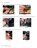
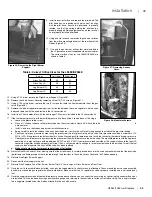
24.  Reinstall access cover (removed in Step 22) from inside the firebox.

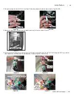
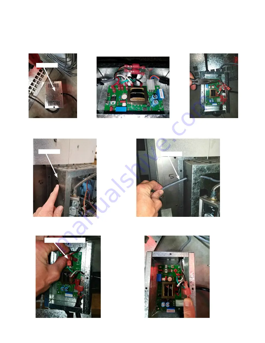
25.  Remove cover plate off of Power Vent Control box (4 screws) Figure 21a, note the proper position of all wire connections prior to removing Figure 21b
(they will need to be reinstalled exactly as removed in later steps), then carefully remove only the wires from the 

grey sleeved

 wire harness from the board 

shown in Figure 21c. Do not disconnect any of the other remaining wires.

26.  Locate the plastic grommet on the front top side of access panel and feed grey sleeved wires (disconnected in the previous step) through it as shown in 

Figure 22a & 22b.

27. Bring the grey sleeved wire harness to the PVC board and Carefully reconnect all wires onto the PVK board & reinstall cover plate shown in Figure 23a & 23b.

Figure 21c

Figure 21b

Figure 21a

Figure 22a

Figure 23a

Figure 23b

Figure 22b

Cover Plate

Grommet

Reconnect all wires

Gray Wire

36

    |     HZ965/L965 Gas Fireplace

 | 

36

installation

Summary of Contents for Horizon HZ965E

Page 1: ...touch any electrical switch do not use any phone in your building Immediately call your gas supplier from a neighbour s phone Follow the gas supplier s instructions If you cannot reach your gas supplier call the fire department FPI FIREPLACE PRODUCTS INTERNATIONAL LTD 6988 Venture St Delta BC Canada V4G 1H4 919 503d 08 03 17 Owners Installation Manual Tested by Installer Please complete the detail...

Page 2: ... performed by a qualified installer service agency or gas supplier This installation must conform to local codes or in the absence of local codes to the current CAN CSA B149 1 Natural Gas and Propane Installation Code Canada or National Fuel Gas Code ANSI Z223 1 2 USA To prevent injury do not allow anyone who is unfamiliar with the fireplace to operate it To prevent injury if the pilot or pilot an...

Page 3: ... 41 LP Gas Conversion 42 Glass Burner Removal installation 45 Glass Crystal stones installation 46 Optional Spa Stones Installation around burner 46 Reflective panel installation Removal 47 Brick panel installation Removal 48 Log Burner Ember Bed Removal Installation 49 Log set installation 49 Safety Screen Installation 52 Finishing trim 53 Start Up Operation 54 Normal Sounds During Operation 54 R...

Page 4: ...e with either natural or propane gases See rating label Is not for use with solid fuels Is approved for bedroom or bed sitting room IN CANADA must be installed with a listed wall thermostat IN USA see current ANSI Z223 1 for installation instructions Must be installed in accordance with local codes If none exist use current installation code CAN CSA B149 1 Natural Gas and Propane Installation Code...

Page 5: ...rovided and fastened to the right side of the fireplace Power needs to be brought to the electrical junction box The power for the various control components are all provided from the fan control module Install the provided electric outlet and cover and plug the the fan control module into it See the Rating Label for the listed electrical requirements When installed the L965E HZ965E must be electr...

Page 6: ...certifee est utilisee ADVERTISSEMENT Ne pas utiliser l appareil tant que toutes les sections n ont pas ete assemblees et installees selon les instructions du fabricant MOBILE HOME May be installed in an aftermarket permanently located manufactured home USA only or mobile home where not prohibited by local codes See owner s manual for details This appliance must be installed in accordance with the ...

Page 7: ...lling your new L965E HZ965E Some options include external chases internal chases rock facing and corner installations No matter what direction your installation takes this illustration shows an area where no combustible building products may go This illustration applies to any and all installations for the L965E HZ965E and should be used as the first reference before any others Failure to comply w...

Page 8: ...mm Minimum 52 5 16 1329mm To Header 44 3 4 1137mm Minimum Figure 5 Typical Framing for Internal Chase General FRAMING INTERNAL CHASE NOTE Framing chase depth is 26 1 2 when using the heat distribution kit Internal ceiling clearance is 90 when using the heat distribution kit 8 HZ965 L965 Gas Fireplace 8 installation ...

Page 9: ... 610mm Min Chase Depth 52 5 16 1329mm To Header 44 3 4 1137mm Minimum EXTERNAL CHASE Non Combustible Facing and Hearth Protector Dimensions Facing supplied 1 Top 46 x 19 2 Sides 32 15 16 x 4 9 16 Hearth Protector supplied 46 x 12 NOTE No hearth is required if the unit is raised a minimum of 18 off the floor HZ965 L965 Gas Fireplace 9 9 installation ...

Page 10: ...ming for Corner Detailed 44 3 4 1137mm Minimum 52 5 16 1329mm Minimum to Header Shelf Height from Base of Unit 64 1626mm Figure 9 Typical Framing for Corner General CORNER FRAMING 10 HZ965 L965 Gas Fireplace 10 installation ...

Page 11: ...every 1 25 4mm of height it is installed over the minimum height as shown in Figure 12 Non combustible mantels and mantel legs are not limited to these dimensions Mantel temperatures are monitored during testing and can reach 117 F 47 C above room temperatures Make sure the finish on your mantel is suitable for temperatures of this range A wood trim can overhang a maximum of 1 1 4 deep and 14 1 2 ...

Page 12: ...ble slate A The thickness of the riser B is 4 102mm The thickness of the slate A is 2 52mm A B C which is 6 152mm In summary the fireplace must be raised by the same thickness of any material added in front of the fireplace If the raised hearth is deeper or wider than the Insulation Board provided with the unit additional non combustible materials such as Backer Board cement board can be used to b...

Page 13: ...light the relationships between the fireplace optional front and facing installed Figure 17 Option 1 Fireplace Facing Less Than 1 25 4mm Thick NOTE REQUIRES 5 8 16mm _AIR GAP INSTALLATION OF FIREPLACE FACING Fireplace Door Non Combustible Board Supplied Tile or other non combustible facing including grout or cement 1 2 13mm Any Thickness Figure 18 Option 2 Fireplace Facing More Than 1 25 4mm Thick...

Page 14: ...located Because of the 8 ft 2 4m limitation in the wiring harness the receiver needs to be mounted to the right side of the fireplace An electrical box is provided for the receiver Mount this electrical box as you would any electrical outlet or switch box Thread the cable and connector through the back of the electrical box and connect it to the rear of the receiver Secure the receiver into the el...

Page 15: ...nting that is approved for this appliance Flex vent runs must comply with the same limitations as the rigid vent chart shown here Flexible vent runs greater than 10 total are not permitted When using the flexible vent system part 946 601 5 x 8 flex pipe adaptor must be used to adapt from rigid venting to flex venting This must be attached to the appliance prior to attaching flex venting The restri...

Page 16: ...12 in 30 cm Clearance from permanently closed window to prevent condensation D 19 in 49 cm Vertical clearance to ventilated soffit located above the terminal within a horizontal distance of 2 ft 60 cm from center line of terminal E 19 in 49 cm Clearance to unventilated soffit F 17 in 44 cm Clearance to outside corner G 17 in 44 cm Clearance to inside corner H 3 ft 91 cm within a height of 15 ft 4 ...

Page 17: ...C 5DHT TM 5HT TM 5DHT Horiz Round Termination 5DHC Horizontal Sconce Termination Vert Termination High Wind 58DVA VCH SV5CGV 5DVC 5DT VT 5DVT Vinyl Siding Standoff 58DVA VSS SV5VS 5DHVS 5DT VS 5DVS TM VSS Flex Venting 5 and 8 Duraflex Several color choices IMPORTANT This chart covers the major components for each of these manufacturers only Refer to the manufacturers catalogue for further details ...

Page 18: ...at a 40 restrictor restricts the vent 40 from its fully un restricted vent size 1 Remove the Glass Door refer to Door Removal and Installation 2 Remove the Burner and or Log Set refer to Burner Removal and Installation 3 Remove the Reflective or Brick Panels refer to Reflective or Brick Panel Installation 4 Refer to the Vent Chart Figure 23 for selection of the appropriate Restrictor 5 Using the t...

Page 19: ...above the mantel within 4 inches 102mm of the wall was measured under maximum operating conditions and found to not exceed 120 F 49 C Variations of mantel overhangs shelf depths or ceiling heights will affect this temperature Please refer the TV owner s manual for information on acceptable operating conditions Care must be taken to evaluate your specific installation and operating conditions when ...

Page 20: ...loor level If an offset is needed in the attic additional pipe and elbows will be required ASSEMBLY OF THE UNIT 1 Using eight 8 T 20 screws provided install the facing supports right and left as well as the heat shield in the middle as shown in Figure 28 2 Using eight 8 T20 screws provided attach both back stand offs as shown in Figure 29 SECURING UNIT INTO POSITION Once the unit is in its final p...

Page 21: ...NSTALLATION OF VENTING AND TERMINATIONS Read all instructions carefully before starting the installation Failure to follow these instructions may create a fire or other safety hazard and will void the warranty INSTALLATION PRECAUTIONS Do not install any damaged venting or vent components Do not modify any vent or termination component Do not install any vent component that is not an approved vent ...

Page 22: ... center of the square hole should line up with the centerline of the horizontal pipe as shown in Figure 35 Cut and frame the square hole in the exterior wall where the vent will be terminated If the wall being penetrated is constructed of non combustible material i e masonry block or concrete a hole with zero clearance to the pipe is acceptable Notes 1 Any horizontal run of vent must have a inch 6...

Page 23: ...rk the location where the vent will penetrate the ceiling Drill a small hole at this point Next drop a plumb bob from the roof to the hole previously drilled in the ceiling and mark the spot where the vent will penetrate the roof Determine if ceiling joists roof rafters or other framing will obstruct the venting system You may wish to relocate the appliance or to offset to avoid cutting load beari...

Page 24: ...ofline Step 7 Continue to add Pipe Sections until the height of the Vent Cap meets the minimum building code requirements described by your local codes In the absence of local codes make sure the terminal is 2 feet 610mm above anything within 10 feet 3046mm of the vent refer to Figure 44 Table 5 for clearances for different pitches Note that for steep roof pitches the vent height must be increased...

Page 25: ...X Regency Direct Vent System These venting systems in combination with the HZ965 L965 have been tested and listed as a direct vent system by Warnock Hersey The location of the termination cap must conform to the requirements in the Vent Terminal Locations diagram from the Exterior Vent Termination Locations section FPI Direct Vent Flex System Termination Kits include all the parts needed to instal...

Page 26: ...nt Duct 4 Fan Bezel 5 Front Access Cover 6 Fan 7 Fan Housing Assembly 8 Fan Housing Mounting Bracket 9 5 Round Flex Line Air Duct Figure 2 Remove the duct cover 2 Insert the hot air duct and the hot air duct angle into the cut out refer to Figure 3 Secure the ducts to the back of the fireplace through the pre drilled holes with hex head Figure 3 Install the hot air ducts screws 3 Cover the hot air...

Page 27: ...Duct Vent Duct Collar Fireplace Figure 5 Fan housing overall dimensions Figure 6 Minimum Installation Clearances for Fan 5 Mount and secure the fan housing assembly to the framing members or to the 2x4 wall studs using the mounting brackets and screws provided in the kit refer to Figure 7 Note The brackets have a guided flange which provides the minimum spacing required between the fan housing and...

Page 28: ... the total run 20 which is the maximum allowable 9 Attach the fan bezel to the fan cut out and secure the fan bezel to the wall board with screws 10 Cover the cut out with a fan grille Wheninstalled thePowerVentKit mustbeelectrically grounded in accordance with local codes or in the absence of local codes with the National Electrical Code ANSI NFPA 70 or the Canadian Electrical Code CSA C22 1 Fan ...

Page 29: ...nternal Ceiling 60 1524mm Chase Minimum Width 44 3 4 1137mm Minimum 26 1 2 610mm Chase Minimum Depth Minimum Height from the base of the unit Figure 12 Installation Clearances with Heat Distribution Kit HZ965 L965 Gas Fireplace 29 29 installation ...

Page 30: ... Multi elbow installations are possible up to a maximum of six 90 See Figure 4a for the typical overall dimensions with a minimum horizontal vent installed Refer to Figure 19 and Table 1 for vent termination clearances and restrictions Approved vent systems are as follow when using 4 x 6 5 8 pipe Simpson duravent Security Chimney American Metal Selkirk Int Metal Fab Excel Direct Item Description 1...

Page 31: ... power vent electrical cord through the bushing on the bottom left of the inner thimble shown in Figure 6 5 Secure the inner thimble to the wall board with screws 6 Insert the rest of the power vent electrical cord through the bushing on the right bottom of the outer thimble refer to Figure 7 391 16 992mm 44 1 11m 97 16 240mm 141 8 359mm 5 x 8 90o Elbow 1ft 305mm 4 x 6 Vent 5 x 8 to 4 x 65 8 Vent ...

Page 32: ...downward on power vent case cover to clear exhaust assembly 9 Insert the power vent electrical cord through the Strain Relief on the bottom right of the power vent assembly refer to Figure 8 10 Align the power vent assembly with the direct vent pipe that is protruding through the thimble 11 Secure the power vent assembly in place with screws as seen in Figure 8 Inner Thimble Power Vent Electrical ...

Page 33: ...shown in Figure 9 Route the wires as shown in Figure 10 to prevent them from getting pinched 14 Align the exhaust deflector with the exhaust cut out on the bottom of the power vent cover and install refer to Figure 8 11 and 12 Ensure that the rubber vacuum hose does not kink when installed 15 Secure the cover to the power vent assembly with screws to the left and right sides of the assembly 16 Fro...

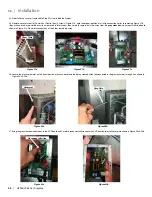
Page 34: ... pilot so locate the CPI IPI connectors Blue and White wires and disconnect them as shown in Figure 16a 16b 20 Locate the Green TH wire connection and disconnect as shown in Figure 17a 17b Figure 15a 9V clips Figure 16a Figure 17a Figure 15b Figure 16b Figure 17b 9V clip from PVK CPI IPI switch Green TH wire CPI IPI switch disconnected 9V clip from unit 9V clips connected 34 HZ965 L965 Gas Firepla...

Page 35: ...valve and carefully connect Blue wires from PVK to EV1 and Orange wire NOTE gas valve has been removed from unit to better show the wire connections Shown in Figure 20a 20b 20c 20d Orange wire Orange wire EV1 Blue wire connected to EV1 Orange wire disconnected Blue wire connected to Orange wire Blue wire Inside access cover Orange wire Green TH wire Green TH wire Figure 18a Figure 19 Figure 20a Fi...

Page 36: ...oard shown in Figure 21c Do not disconnect any of the other remaining wires 26 Locate the plastic grommet on the front top side of access panel and feed grey sleeved wires disconnected in the previous step through it as shown in Figure 22a 22b 27 Bring the grey sleeved wire harness to the PVC board and Carefully reconnect all wires onto the PVK board reinstall cover plate shown in Figure 23a 23b F...

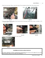
Page 37: ...shown in Figure 26 WARNING Electrical Grounding Instructions This appliance is equipped with a three prong grounding plug for your protection against shock hazard and should be plugged directly into a properly grounded three prong receptacle Do not cut or remove the grounding prong from this plug Periodic examination of venting systems should be done by a qualified agency Figure 24b Figure 24a Fig...

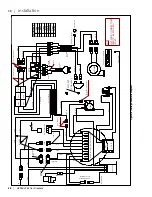
Page 38: ...T BLUE IN N O SW IPI CPI TPTH TH COM TRIGGER GROUND FCM COM DFC SUPPLY TH BATTERY SPLIT FLOW DFC MOTOR C 11974 2ft C 11896 50ft 50 1970 WESTGATE 2 ft C 11817 1ft 3 16 Spades 0 187 3 16 Female Spade 0 187 3 Insulated BROWN ORANGE BLUE OUT BLUE IN 1 4 Male Spades August 25 2009 NOTE ALL SPADE CONNECTORS NEED TO BE SPACED 1 APART Star Washer 4 6 prongs snap 6 prongs snap COM ONG GRN ONG CN1 MOLEX 1 R...

Page 39: ...2 in 30 cm Clearance from permanently closed window to prevent condensation D 4 in 10 cm Vertical clearance to ventilated soffit located above the terminal within a horizontal distance of 2 ft 60 cm from center line of terminal E 4 in 10 cm Clearance to unventilated soffit F 12 in 30 cm Clearance to outside corner G 4 in 10 cm Clearance to inside corner H 3 ft 91 cm within a height of 15 ft 4 5 m ...

Page 40: ...rds and then remove the door latch tool Refer to Figures 47 48 3 Pull the Door Frame at the bottom forward about 2 5cm then lift the Door Frame upwards to clear the Upper Door Hooks Refer to Figures 48 49 4 Lift the Door Frame away being careful that the glass panel is secure within the Door Frame Large hooked end for removing the door Slots on other end is for Air Shutter Adjustment Levers Figure...

Page 41: ... kPa 14 5 8 371mm 1 2 SAE 45 Flare Fitting Gas Inlet 14 3 4 375mm 19 3 4 502mm Figure 50 Location of Gas Hook Up WARNING Electrical Grounding Instructions This appliance is equipped with a three prong grounding plug for your protection against shock hazard and should be plugged directly into a properly grounded three prong receptacle Do not cut or remove the grounding prong from this plug An elect...

Page 42: ... orifice left right for the glass tray orifices left right for the log burner orifices regulator diaphragm servo regulator and conversion label 2 If the unit has already been connected to a gas supply shut off the gas supply to the unit 3 If the unit has been run shut off and allow cooling to room temperature 4 Remove the fireplace door see Door Removal and Installation 5 Remove the burner glass c...

Page 43: ...he inlet pressure tap on the valve Inlet pressure should be a minimum of 12 WC for LPG If the pressure reads less than this have a licensed gas fitter determine and rectify the reason for the reduced supply pressure f Check your manifold pressure by measuring the pressure at the manifold pressure tap on the valve The manifold pressure with the appliance operating at its high setting should be betw...

Page 44: ...ress the ON button on the remote control b The receiver should beep to indicate the command has been received c Within a 2 3 second of the beep the ignitor should begin to spark The ignitor will spark at intervals of 1 second s d The main valve will open 4 6 seconds after the pilot is lit e Within 4 seconds of the main valve opening all of the burner ports should light and remain burning 26 To com...

Page 45: ...mixing tubes lift the burner up and out 5 To install reverse steps 2 After the screws are removed lift out the front panel as shown in Figure 63 3 Remove the 4 screws on the burner in locations shown in Figure 64 Figure 63 Lift Out Front Panel Figure 64 Burner Screw Locations Figure 65 Move Burner away from Mixing Tubes Figure 62 Removing Front Panel Screws Figure 61 Front Panel Screw Locations HZ...

Page 46: ...orts or pilot light that lead to pilot flame Ensure the crystals or stones do not overlap excessively as this will effect the flame pattern 1 Start Crystals on back Burner and Firebox Floor 2 Work Crystals downwards to front of Burner and Firebox Floor 3 Work Crystals downwards to front edge of Firebox Floor 4 Crystals shown spread evenly over the burner and firebox base 5 Ensure Crystals do not b...

Page 47: ...eaner to remove any fingerprints before applying heat to the unit Failure to do this will result in burn stain on panels which you will be unable to remove Not protected by product warranty Figure 74 Rear Porcelain Panel Figure 75 Side Porcelain Panel and Panel Clip Figure 76 Panel Unit Alignment Figure 77 Upper Rear Porcelain Panel Figure 78 Final Install 2 Install the Left Reflective Panel it sh...

Page 48: ...nd on top of the lower back panel as shown in Figure 79 Figure 77 Lower Back Brick Panel Figure 80 Right Side Brick Panel Figure 81 Completed Install Figure 79 Upper Back Brick Panel Figure 78 Left Brick Panel Install Figure 76 Brick Clip BRICk PaneL InStaLLatIon RemovaL 3 Slide Left Brick Panel in between wall of unit and Brick Clip as shown in and Figure 78 Front edge of panel must be flush with...

Page 49: ...G F C Read the instructions below carefully and refer to the images If the logs are broken do not use the unit until they are replaced Broken logs can interfere with pilot operation Improper positioning of the logs may create carbon build up and can alter the unit s performance which is not covered under warranty Satin black paint is included if touch ups are required Completed Install LOG SET INS...

Page 50: ...fy locator on Log B as shown in Figure 87 3 Line up Locator on Log B with Locator on Log A as shown in Figure 88 Figure 86 Log A Figure 89 Log A Locator Figure 90 Log C Position B Locator Figure 87 Log B Locator Figure 88 Log B Position 6 Identify locator on Log D and opposing Locator on Log B as shown in Figure 91 Place Log D gently on Log B Figure 91 Log D Locator D B 50 HZ965 L965 Gas Fireplace...

Page 51: ... 9 Identify locator on Log G and opposing Locator on the Ceramic Log Burner as shown in Figure 94 Place Log G gently on Burner 10 Identify locator on Log H and opposing Locator on Log B as shown in Figure 92 Place Log H gently on Log B 11 Log H in position Figure 92 Log F Locator Figure 93 Log F Locator Figure 95 Log F and G position Figure 94 Log G Locator Figure 96 Log H Locator Figure 97 Log H ...

Page 52: ...SAFETY SCREEN INSTALLATION 52 HZ965 L965 Gas Fireplace 52 installation ...

Page 53: ...e unit and the non combustible materials FINISHING TRIM Figure 100 Top View exposed non combustible materials Figure 101 Top View Sliding trim into place Figure 102 Completed Trim install 1 Slide trim into position over exposed non combustible materials Non combustible materials Trim piece HZ965 L965 Gas Fireplace 53 53 installation ...

Page 54: ...AL RANGE ATTENTION TURN OFF THE MAIN GAS SUPPLY OF THE APPLIANCE DURING INSTALLATION OR MAINTENANCE OF THE RECEIVER PLACE THE RECEIVER S 3 POSITION SLIDER SWITCH IN THE OFF POSITION DURING INSTALLATION OR MAINTENANCE TURN OFF MAIN GAS SUPPLY TO THE APPLIANCE PRIOR TO REMOVING OR REINSERTING THE BATTERIES IN THE RECEIVER DURING APPLIANCE INSTALLATION MAINTENANCE OR IN CASE OF REMOTE CONTROL MALFUNC...

Page 55: ...accepts commands via radio frequency from the Transmitter to operate the appliance in accordance with the particular Proflame system configuration The Receiver three 3 position slider switch can be set to one of three positions ON Manual Override Remote Remote control or Off Figure 103 Proflame Transmitter Figure 104 Proflame Transmitter LCD Screen Figure 105 Proflame Receiver Split Flow FAN CONTR...

Page 56: ...e Transmitter push the ON button The Receiver will beep four 4 times to indicate the Transmitter s command is accepted and sets to the particular code of that Transmitter The system is now initialized Temperature Indication Display With the system in the OFF position press the Thermostat Key and the Mode Key at the same time Look at the LCD screen on the transmitter to verify that a C or F is visi...

Page 57: ...w Key will increase the flame height each time it is pressed If the Up Arrow Key is pressed while the system is on but the flame is off the flame will come on in the high position refer to Figure 107 A single beep will confirm reception of the command REMOTE ACTUATED ACCENT LIGHTS The L965E is shipped with two 2 firebox accent lights They are connected to the auxiliary power outlet of the Proflame...

Page 58: ...e on SPLIT VALVE OPERATION The split flow operation on the L965E HZ965E turns off the rear section of the burner greatly reducing the heat output of the unit If you d like to have the fireplace on but would not like Figure 113 Remote Control Locked Figure 114 Low Battery Indicator to have as much heat in the room you can turn off this function Press the bottom key of your remote repeatedly until t...

Page 59: ... the gas flame burns with a blue base and a bright yellow upper section Air shutters set to closed will lead to a dirty flame which may lead to soot gathering on the logs and or glass panel Properly set Air Shutters will result in a very blue flame for the first fifteen 15 minutes of operations with the flame becoming more yellow as the unit comes up to operating temperature Table 2 Air Shutter Se...

Page 60: ...SS Caution Label all wires prior to disconnection when servicing controls Wiring errors can cause improper and dangerous operation Verify proper operation after servicing 60 HZ965 L965 Gas Fireplace 60 maintenance ...

Page 61: ...d unité au Plafond 80 inches 203 2cm From fireplace frame 25 5 cm From base of the unit to shelf header or 12 30 5c ou un 12 manteau de cheminée 52 25 133cm VENT PIPE CLEARANCES ESPACES LIBRES DE VENTILAT instructions Verifeez l identifaction l etiquette et les instruction connected to a venting system in accordance with the manufac convenablement connecté à un système donner vent conformé VENTED ...

Page 62: ...ormal condition with all fireplaces However this condensation can allow dust and lint to cling to the glass surface Initial paint curing of the appliance can leave a slight film behind the glass a temporary problem The glass will need cleaning about two weeks after installation Use a mild glass cleaner and a soft cloth abrasive cleaners will damage the glass and plated surfaces Depending on the am...

Page 63: ...ice Pilot will not remain lit Problem with Flame Sensor circuit Check for proper connection of the Flame Sensor to the DFC board Check pilot for full flame impingement around Flame Sensor If flame is too small check gas pressure adjust pilot rate screw check pilot head for damage Ensure the ground wire is properly attached to the pilot mounting bracket and that it is makes a good electrical connec...

Page 64: ...ng to thermostat for breaks Check for flame impingement on thermopile Flame lifting Leak in vent pipe Check for leaks in vent connections Improper vent configuration Check vent configuration with manual Terminal may be re circulating flue gases Check to see if terminal is on correctly May need to install high wind termination cap Contact dealer Blue Flames The heater has just been started Normal d...

Page 65: ...when installing a raised hearth you can install the unit observing the clearances outline in this diagram The main difference is the install depth is changed to 26 673mm to compensate for the reduced vertical clearances The width and framing dimensions remain unchanged to the regular installations shown earlier in this manual 44 3 4 1137mm 52 5 16 1329mm HZ965 L965 Gas Fireplace 65 65 installation...

Page 66: ...66 HZ965 L965 Gas Fireplace 66 parts list ...

Page 67: ...PI 20 911 006 Pilot Assembly NG 911 007 Pilot Assembly LP 22 706 026 Vent Restrictor Set 27 706 921 Regency Heat Distribution Kit 28 706 922 Power Vent Kit 30 706 540 Safety Screen Item Part Description 36 706 969 LPG Conversion Kit 37 706 968 NG Conversion Kit 38 910 100 Pilot Orifice Injector NG Threaded 39 910 101 Pilot Orifice Injector LP Threaded 910 432 Sit Pilot Tube W end Ferules 1 Pc 706 ...

Page 68: ...nels 1 Venting Venting Components 1 All Stainless steel surrounds 1 All Firebox Media Crystals Firebeads Volcanic Ceramic Spa Stones 1 All hardware 1 Mesh Glass Safety Barriers 1 Accent Light Bulbs 1 Glass Crazing 1 Conditions Warranty protects against defect in manufacture or FPI factory assembled components only unless herein specified otherwise Any part s found to be defective during the warran...

Page 69: ...n unqualified installer incorrect chimney components including but not limited to cap size or type operator error abuse misuse use of improper fuels lack of regular maintenance and upkeep acts of God weather related problems from hurricanes tornados earthquakes floods lightning strikes bolts or acts of terrorism or war which result in malfunction of the appliance are not covered under the terms of...

Page 70: ...plicable to this warranty How to Obtain Warranty Service Customers should contact the authorized selling dealer to obtain warranty service In the event the authorized selling dealer is unable to provide warranty service please contact FPI by mail at the address listed below Please include a brief description of the problem and your address email and telephone contact information A representative w...

Page 71: ...Registration Form or Register online immediately at the above Web Site Warranty Details Serial Number required Purchase Date required mm dd yyyy Product Details Product Model required Dealer Details Dealer Name required Dealer Address Dealer Phone Installer Date Installed mm dd yyyy Your Contact Details required Name Address Phone Email For purchases made in CANADA FPI Fireplace Products Internati...

Page 72: ......

Page 73: ...HZ965 L965 Gas Fireplace 73 73 notes ...

Page 74: ...74 HZ965 L965 Gas Fireplace 74 notes ...

Page 75: ......

Page 76: ...ress ____________________________________ ________________________________________________________ Installer _________________________________________________ Phone _________________________________________________ Date Installed ____________________________________________ Serial No ________________________________________________ Liberty L965E Horizon HZI390E ...

Reviews: