9. Install the correct orifice and replace the pilot hood. The
pilot hood has an indexing notch which must be align
with the pilot base. Ensure the pilot hood is properly
located and that the spring holding the pilot hood is
properly engaged. Delayed ignition may be the result of
an improperly installed pilot hood.
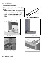
10. Using a socket wrench, remove both gas burner orifices
from the orifice mounting brackets at the rear floor of the
firebox (Figure 55).
11. Use only the gas burner orifices that were included in
the LP gas conversion kit supplied by the manufacturer.
The correct orifice sizes for the L965E/HZ965E are
shown in Table 6.
Table 6: Correct Orifice Sizes for the L965E/HZ965E
Burner
Left (front)
Right (rear)
Glass Tray NG
45
41
Glass Tray LP
55
53
Log Burner NG
45
41
Log Burner LP
55
53
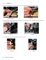
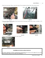
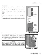
12. Using a T-20 driver, remove the Right Burner Support (Figure 56).
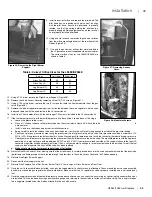
13. Remove the Valve Access Cover by removing all ten (10) T-20 screws (Figure 57).
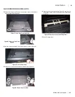
14. Using a T-20 safety driver, remove the two (2) screws that hold the flame modulator from the gas
valve (Figure 58).
15 Remove the rubber regulator diaphragm that is situated between the servo regulator and the valve
body and replace with the one provide in the LP conversion kit.
16. Install the LP flame modulator, with the new longer T-20 screws, included in the LP conversion kit.
17. If the fuel delivery pressure or the manifold pressure is to be verified, it can be done at this stage.
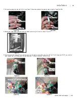
a. Loosen the pressure tap screw.
b. Place a ¼” silicone tube over either pressure port on the valve (refer to Figure 59). Attach the tube
to
a mono meter.
c. Install a burner in the firebox (see burner installation section)
d. Being careful to route the silicone tube away from the burner, test fire the unit for only long enough to establish the pressure reading.
e. Check your inlet gas pressure by measuring the pressure at the inlet pressure tap on the valve. Inlet pressure should be a minimum of 12”
WC for LPG. If the pressure reads less than this, have a licensed gas fitter determine and rectify the reason for the reduced supply pressure.
f. Check your manifold pressure by measuring the pressure at the manifold pressure tap on the valve. The manifold pressure with the appliance
operating at its high setting should be between 9.5” WC and 10.5” WC. If your pressure reads outside of this range, make sure that your LP
conversion regulator has been properly installed. If it has, call your dealer to arrange for a replacement valve to be installed. Turn off the fuel
supply to do not operate this unit until the valve has been replaced.
g. Make sure to close the test pressure point taps after testing.
18. Re-install the Valve Access Cover, making sure that the wire harness is carefully tucked back into the valve compartment and that the pilot tube,
igniter lead and flame proving wire are routed through the provisions in the Valve Access Cover and the Firebox opening.
19. Re-install the Right Burner Support.
20. Re-connect the fuel supply to the unit.
21. Re-install the Fireplace Panel Set, Burner, Burner Trim Kit, Grate, Logs or Glass Burner and Front Door.
22. Once the unit is re-assembled and started, use a gas leakage detector to check for any fuel leakage. Check around the entire valve assembly,
particularly around the gas regulator and flame modulator. Make sure that the LP regulator has been properly installed and is not leaking any
fuel.
23. Once the supply pressure and the manifold pressure have been confirmed, you can check the units rating by confirming the correct orifice sizes
are installed. This can be done by using a quality orifice gauge and referring to the chart above for the correct office sizing. The rating is listed on
the rating plate located under the firebox, attached to the unit with a cable.
Figure 56: Removing the Right Burner
Support.
Figure 57: Removing Access
Cover.
Figure 58: Modulator Screws.
HZ965/L965 Gas Fireplace |
43
43
|
installation
Summary of Contents for Horizon HZ965E
Page 52: ...SAFETY SCREEN INSTALLATION 52 HZ965 L965 Gas Fireplace 52 installation ...
Page 66: ...66 HZ965 L965 Gas Fireplace 66 parts list ...
Page 72: ......
Page 73: ...HZ965 L965 Gas Fireplace 73 73 notes ...
Page 74: ...74 HZ965 L965 Gas Fireplace 74 notes ...
Page 75: ......

