background image

11 

Sentinel Kinetic Advance S, SX - www.regulus.eu

Before installation of the unit
We advise installers to fix all mains and sensor wiring along with any internal accessories prior to 

fixing the unit in position, leaving approximately 500mm tails to allow for internal routing.
Inspect the Unit

When taking delivery of the unit, check the items delivered against the enclosed delivery note. Inspect the 

unit for damage in transit. Each box contains a Kinetic Advance Heat Recovery unit, a wall bracket and 

accessory pack containing miscellaneous fixings and product documentation.

Unit Installation

Installation should be carried out by a suitably qualified and competent person. 
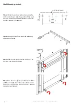
If the unit is wall mounted, the wall should have sufficient strength to support the unit
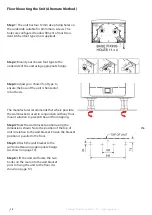
The unit may also be floor mounted, either directly to the floor or using standard kitchen cabinet feet (not 

supplied). Ensure that the unit is mounted upright.
Do not use this unit as a support for any other equipment.
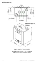
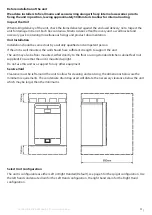
Service Void

Clearance must be left around the unit to allow for cleaning and servicing, the dimensions below are the 

minimum requirements. The condensate drain trap used will dictate the necessary clearance below the unit 

which may be larger than the minimums.

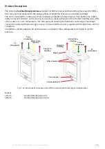
Select Unit Configuration

The unit is configurable as either Left or Right Handed (Default), see page 5 for the spigot configuration. Use 

the left hand condensate drain for the Left Hand configuration, the right hand drain for the Right Hand 

configuration.

Summary of Contents for 16487

Page 1: ...www regulus eu SENTINEL KINETIC ADVANCE SENTINEL KINETIC ADVANCE EN Installation and Commissioning Instructions SENTINEL KINETIC ADVANCE S SX...

Page 2: ...qualified person after completion 3 Ensure the mains supply voltage frequency and phase complies with the rating label 4 The unit should be provided with a local double pole fused spur fitted with a 3...

Page 3: ...be allowed to stabilise during commissioning for a minimum period of 5 minutes when changing between boost and normal speeds 9 Ensure that the unit s external grilles openings are at least 1000mm apa...

Page 4: ...rge Condensate Installation 15 Attach the Ducting 16 Electrical Installation 17 Connect Switches and Sensors 18 Connect the Power Supply 20 Commissioning 21 Powering up the Unit 21 Overview 21 Control...

Page 5: ...ign concept provides significant energy recovery on household heat costs coupled with the optimum comfort conditions In addition a Kinetic Advance SX unit maintains a constant airflow independent of c...

Page 6: ...inel Kinetic Advance S SX www regulus eu Product Dimensions Figure 2 Sentinel Kinetic Advance Dimensions Remove front cover see page 17 to view Rating label Label is positioned to the right of the con...

Page 7: ...m3 h at 150 Pa Power AC Voltage Input 220 240 V AC single phase AC Frequency Input 50 Hz nominal Supply Fuse code 9532 Product Fuse 2 A located on main PCB Rated Power max 190 W Physical Height excl s...

Page 8: ...ach mode is set independently and not defined by the mode name When setting up Over Pressure or Fireplace Mode the supply rate must be set higher than extract rate This is to provide a positive intern...

Page 9: ...s will operate Indoor temp should be set 2 3 C higher than the central heating thermostat to prevent the bypass operating in winter and 2 3 C lower than any air conditioning thermostat if fitted Outdo...

Page 10: ...ccessory The optional Switched Live LS expansion accessory offers two extra switched live inputs LS2 and LS3 for boosting via light switches 220 240V AC or Normal Boost switch This connection has the...

Page 11: ...lified and competent person If the unit is wall mounted the wall should have sufficient strength to support the unit The unit may also be floor mounted either directly to the floor or using standard k...

Page 12: ...to the wall bracket Ensure the bracket position is horizontal Step 2 Attach the wall bracket to the wall using appropriate fixings Step 3 Lift the unit and locate the two hooks on the rear onto the w...

Page 13: ...the wall bracket is used in conjunction with any floor mount solution to prevent the unit from tipping Step 2 Mark the wall bracket position using the dimensions shown Note the position of the top of...

Page 14: ...of the unit is horizontal in both axis The manufacturer recommends that where possible the wall bracket is used in conjunction with any floor mount solution to prevent the unit from tipping Step 4 Ma...

Page 15: ...nditions occur outlet pipes must be insulated to avoid blockage by ice which may cause damage to the unit and surroundings This installation guide is for a Right Hand configured unit as specified on p...

Page 16: ...nsate outlet Ensure the sealing gasket is fitted inside the blanking cap Attach the Ducting 1 Always use a short piece of insulated flexible duct maximum 150 mm long extended to its full length when c...

Page 17: ...sliding it upwards and away from the unit Step 3 Remove the two screws on either side of the access panel Lift the panel outwards from the bottom edge to remove Note The access panel is tethered on th...

Page 18: ...EMC engineering practice any sensor switched live or Volt free cables should not be installed within 50 mm of other cable or on the same metal cable tray as other cables Connect any switches or sensor...

Page 19: ...ode Output A 5 V LED driving signal output between the and terminals that enables remote indication of a unit fault DIAG Diagnostic Diagnostic port USB USB Commissioning port LS1 Switched Live 220 240...

Page 20: ...n the manner shown above Connect the other end of the cable via a 3A circuit breaker code 9532 Use cable clamps and clips to secure the cable as appropriate Connecting a Boost Light Switch A Switched...

Page 21: ...the system is installed according to the system designers intent incorporating any acoustic ducting that all joints are air tight ducting is well supported bends are avoided close to vents and that th...

Page 22: ...The user menu home screen consists of a User Mode LOW BOOST PURGE button a Machine status bar and a Settings Performance bar The Machine status scrolls through Mode of operation Summer bypass status...

Page 23: ...following pages show all available settings within the commissioning menu Please note that some settings may not be available or may be in a different order due to pre configuration by your distribute...

Page 24: ...24 Sentinel Kinetic Advance S SX www regulus eu...

Page 25: ...Load USB Settings Settings can be automatically loaded to the unit via the USB port Note This option will only appear on the Quick Start sequence Access to this screen can be obtained by using the Re...

Page 26: ...description of the unit handling Press to save and return to the commissioning menu Filter Check Select the time interval for checking the filters using the buttons on the screen between 1 month and...

Page 27: ...ble Scroll through the settings using the buttons and select the mode pre set for each User mode Press to save and return to the commissioning menu User Mode Adjust the supply and extract airflows for...

Page 28: ...iffer from image shown depending on unit specification Select the Port to view the Go To Mode speed setting Delay and Over run parameters Select the parameters to edit them Scroll through the settings...

Page 29: ...he buttons on the screen Outdoor Temperature The outdoor temperature is the minimum air temperature that the bypass will permit This is to prevent cold draughts Change the indoor temperature using the...

Page 30: ...elative humidity setback feature suppresses nuisance tripping as humidity gradually increases with falling temperature Go to Mode Scroll through the settings using the buttons and select the required...

Page 31: ...balanced mode must also be used when a combustion device without a dedicated air supply is present Airflow Imbalanced Airflow mode reduces the Intake flow and increases the Extract flow in varying pr...

Page 32: ...the buttons and select the Go To mode for each Schedule Days Scroll through the days of the week using the buttons and select each day to be included in the Schedule program Time Span Adjust the start...

Page 33: ...ory and will be retained irrespective of mains supply breaks however the unit can also be restored back to factory defaults at this screen Press EXIT to return to the User Menu Home screen To complete...

Page 34: ...Screens Summary The following Control Unit screens are available for daily operation and monitoring of the unit Refer to installation and Commissioning guide for further information on these settings...

Page 35: ...35 Sentinel Kinetic Advance S SX www regulus eu Control Unit Screens Summary The following Control Unit screens are available in the Settings Performance section...

Page 36: ...oll through the pre defined user modes factory defaults are BOOST LOW and PURGE using the buttons either side of the User Mode button Select the required function by pressing the centre button When a...

Page 37: ...Menu Diagnostics Days Run and Filter check are reported values and do not have editable parameters in this section Performance The performance menu shows key performance indicators such as recovered...

Page 38: ...ES Press LATER to return to the Settings Menu Display Settings Change the brightness of the touch screen using the buttons Summer Bypass See page 9 for a full description of the Summer Bypass modes an...

Page 39: ...he buttons and select the Go To mode Note Number of available modes may differ from image shown depending on bypass setting and the modes set in the commissioning process Mode Scheduling Use a schedul...

Page 40: ...speed up above the set Maximum Mode Silent Hours can be set to reoccur on specific days and times Service Phone The service phone number can be entered by the installer and should be used if the unit...

Page 41: ...ing the Unit via USB When carrying out commissioning on multiple similar installations commissioned settings may be downloaded and saved onto a USB at the end of the setup routine see page 34 They can...

Page 42: ...oint 70 Control Mode Normal Frost Protection Airflow Mode Mode schedule 1 All days set to 0 00 on 00 00 off inactive Mode schedule 2 All days set to 0 00 on 00 00 off inactive Service Phone Not Set Se...

Page 43: ...devices equipped with Bluetooth 4 0 and running Android 4 3 Jelly Bean or later Follow the instructions in the App to connect with the WiFi unit UNDERSTANDING THE PRODUCT LABEL AP SSID The name of the...

Page 44: ...ent Axia support for further assistance Solid Purple Network controller update mode Should not appear in normal operation Solid Red Communications fault between mainboard and WiFi controller Slow Flas...

Page 45: ...hrough The rate at which the filters become dirty will vary hugely depending on the environment and the activity within the property See page 47 for a list of spare filters 1 Open the filter drawers b...

Page 46: ...he heat exchanger out from the unit Step 4 Wash the outer cover and heat exchanger in warm water using a mild detergent and dry thoroughly NOTE Keep water away from all electrical components and wirin...

Page 47: ...47 Sentinel Kinetic Advance S SX www regulus eu Spares The following spare parts may be ordered from the manufacturer Under preparation...

Page 48: ...tance contact the service provider and quote the fault code number and the product serial number which can be found behind the front cover Note that the fault code is not displayed until the fault has...

Page 49: ...49 Sentinel Kinetic Advance S SX www regulus eu This page is intentionally blank and can be used for making notes regarding the product fiche...

Page 50: ...50 Sentinel Kinetic Advance S SX www regulus eu This page is intentionally blank and can be used for making notes regarding the product fiche...

Page 51: ...trol Factor CTRL 0 65 Control Typology Local Demand Control Declared Max Internal External Leakage Rates 5 Internal 5 External Mixing Rate of Non Ducted BVUs not intended to be equipped with one duct...

Page 52: ...cted during operation that are set by the Installation and Commissioning Instructions generally binding regulations or technical standards and shown on the product itself The warranty especially does...

Reviews: