background image

17

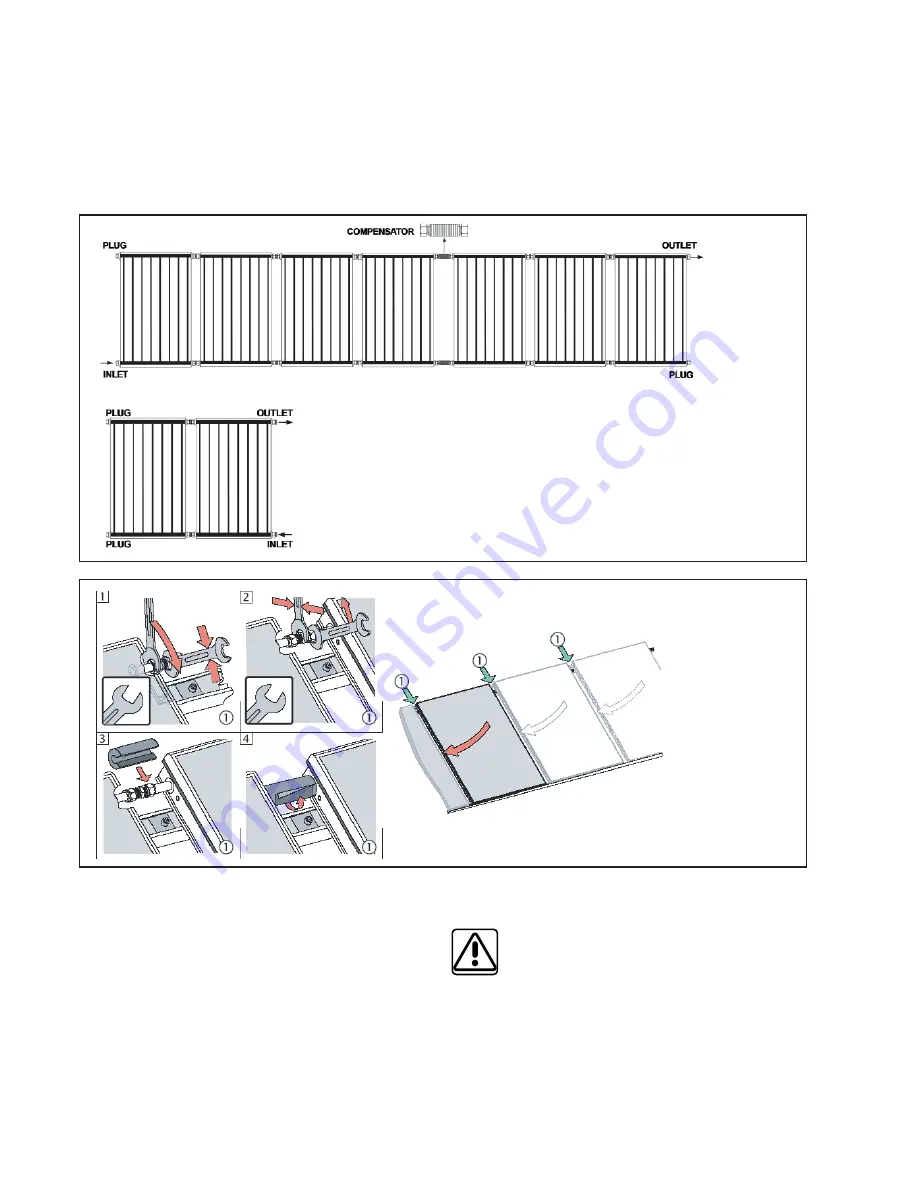
Fig. 22a: 
The recom-
mended 
method of 
collector 
intercon-
necting

Fig. 22b: 
Alternative 
one-sided 
connection 
method

Fig. 23: Col-
lector con-
necting (the 
pic. shows 
connection 
of the upper 
fi tting; the 
lower fi tting 
shall be 
connected 
and tighte-
ned in the 
same way.)

Collectors may be also connected as shown in Fig. 22b. 
This kind of connection is permitted when only 

max. 2 

collectors

 are used and 

the max. fl ow rate is 1l/min/

collector

. Then the cold liquid inlet is at one side bottom 

and the hot liquid outlet is at the same side top. Both the 
other ends shall be plugged.
At the inlet into a collector array, a brass elbow shall be 
installed with a reducing piece to the connecting pipe. 

A brass X-piece shall be installed to the outlet from the 
collector array that will enable connection to the piping, 
sheath installation for the collector temperature probe 
and eventual installation of a ball valve and an automatic 
air discharge valve. The brass elbow and X-piece are 
involved in Regulus connection kit, code 7710 and in 
Connection kit for landscape installation, code 14134 

All solar components must be carefully and safely sealed 
and must be made of material resistant to glycol and 
temperatures up to 160 °C. For connection piping we 
recommend using KOMBIFLEX stainless-steel 

fl

 exible 

pipes, or copper pipes connected by soldering.

In no event plastic tubes can be used for inlet/outlet 
piping as they do not meet the operation requirements 
for solar systems.

Pipes for collectors can be lead through disused chim-
neys, ventilation shafts or grooves in a wall. In order to 
prevent high thermal losses through convection, open 
shafts shall be properly sealed. Also thermal dilatation 

shall be remembered and pipes 

fi

 tted with compensators 

or other compensation elements. 

Piping shall be connected to the house earthing.

Pipes of the solar system must be 

fi

 tted with thermal in-

sulation, so that thermal dissipation from the pipes does 
not deteriorate a total ef

fi

 ciency of the solar system. The 

thermal insulation must be resistant to temperatures 
up to 160 °C, for outdoor piping also a UV protection is 
essential as well as non-deliquescence of the material. 
For indoor piping, the thermal insulation should be at 
least 13 mm thick, for outdoor piping at least 19 mm.

Summary of Contents for KPG1-ALC

Page 1: ...1 1 Solar System with KPG1 ALC Collectors EN v 1 4 Installation and Operation Manual...

Page 2: ...interconnecting 16 6 Temperature Probe Positioning 18 7 Pump Station 19 8 Expansion Vessel Sizing and Working Pressure Calculation 20 8 1 Expansion vessel sizing 20 8 2 Calculation of a system workin...

Page 3: ...ly con sult the fastening method with a structural statics expert During installation the collectors and accessories shall be handled carefully Defects caused by improper hand ling or DIY installation...

Page 4: ...owing chart by the roof type and roofing material Supports and struts for flat roof installation Code Triangle support strut 15 11979 Triangle support strut 25 10975 Triangle support strut 45 6859 Str...

Page 5: ...m 6949 4 M8 nut for the rails 4 pcs 6 pcs 8 pcs 10 pcs 6925 5 M8 16 bolt with allen head 4 pcs 4 pcs 4 pcs 4 pcs 6926 6 Retaining side bracket 4 pcs 4 pcs 4 pcs 4 pcs 10522 10 Retaining bracket betwe...

Page 6: ...pcs 13695 22 mm nipple blind 2 pcs 2 pcs 13696 Nipple 3 4 M M thick wall 4 pcs 2 pcs 6970 3 4 FF elbow brass 1 pcs 1 pcs 10192 T piece in brass 3 4 FFF 1 pcs 7180 X piece in brass 4x 3 4 F 1 pcs 7184...

Page 7: ...boards can be inserted approx distance between boards 1600 1800 mm For roof tiles just shifting them upwards in the length of the auxiliary board is sufficient see Fig 4 Fit the auxiliary boards to ba...

Page 8: ...r Simply lay the anchor onto the roof tiles and fasten it with stainless steel bolts If the roofing is made of e g copper or zinc pla ted iron then the anchor contact surface shall be isolated using s...

Page 9: ...45 150 7 5 e Roofing bolt for rail fastening RIGHT 10 30 mm Fig 8 Right anchor position with roof tiles c Roof anchor of stainless steel or zinc plated steel for pantiles a Stainless steel anchor on...

Page 10: ...the bottom rail 2 brackets per collector Insert the retaining brackets into the bottom rail about 100 mm from the collector edge Lay the first collector carefully on the rails and align it in the bra...

Page 11: ...en the nuts More on this in chapter 5 Hydraulic Connection Continue mounting further collectors in the same way see page 14 48 6 7 5 For passing the connection pipes through a roof e g ventilation til...

Page 12: ...cs 10 pcs 12 pcs 6925 6 M8x16 stainless steel bolt allen head 4 pcs 4 pcs 4 pcs 4 pcs 4 pcs 6926 7 Retaining side bracket 4 pcs 4 pcs 4 pcs 4 pcs 4 pcs 10522 11 Retaining bracket between 2 collectors...

Page 13: ...bow 1 pcs 1 pcs 10192 T piece in brass 3 4 FFF 1 pcs 7180 X piece in brass 4x 3 4 F 1 pcs 7184 3 4 plug gasket brass for code 7628 1 pcs 7954 1 2 3 4 F M brass hex nipple 1 pcs 6964 Single sheath 7x8...

Page 14: ...es cca 350 mm D2 2 4 4 1660 mm T strut base rails L strut D1 Fig 15 Aligning the rails and mounting the first triangular support Assemble the triangular supports that come partially screwed together F...

Page 15: ...ular supports is similar to that of roof anchors in Fig 2 and the last support shall be located about 350 mm from the ends of both rails After fitting the strut and other supports kip the entire struc...

Page 16: ...e first one maintaining a sufficient gap Then put the threaded fittings on both the upper and lower outlets and push the collector to the already mounted one until stop Hold the fitting with a spanner...

Page 17: ...kit for landscape installation code 14134 All solar components must be carefully and safely sealed and must be made of material resistant to glycol and temperatures up to 160 C For connection piping...

Page 18: ...TIONING Tab 1 Recommended pipe diameters AV23 Flow rate regulator with indicator 2 12 l min 3 4 3 8 air discharge valve and 3 8 ball valve up to 160 C Fig 24 Variants of non typical connections Place...

Page 19: ...0 C No shut off valve shall be installed between a safety valve and collectors Fig 26 Solar Pump Station 1 2 3 4 5 6 7 8 9 10 1 Ball valve on flow line red frame thermometer 0 120 C dial with check va...

Page 20: ...ssure in a solar system bar h height from a pressure gauge to the middle of a col lector field m Adjust the pressure by discharging solar liquid after the pressure test is done 8 3 Calculation of expa...

Page 21: ...from the fluid see pic 29 A ball valve shall be always installed under the automatic air vent valve so that the automatic air vent can be clo sed after the system commissioning Solar liquid leaks can...

Page 22: ...ct the filling pump hoses set the circulation pump s to the highest speed and repeat switching on and off to air bleed the system an air free pump works almost noiselessly watch the system pressure an...

Page 23: ...hecked Once a year preferably during a sunny day it is necessary to check the working order and tight fastening of the collectors verify the system tightness and pressure incl pressure in the expansio...

Page 24: ...22 mm 0 8 mm absorber tube material copper absorber tube dimension 12 8 mm 0 5 mm solar absorptance 94 2 emmisivity 5 2 max working pressure 10 bar max working temperature 120 C stagnation temperature...

Page 25: ...v ztr ta kolektoru KPG1 ALC Collector power output in zero point for G 1000 W m2 is 1839 W Momentary collector efficiency over the aperture area for 1000 W m2 insolation Temperature difference between...

Page 26: ...26 84 70 6 1 1 2151 2010 70 1212 1170 21 21 22 15 CONNECTION DIMENSIONS...

Page 27: ...eck pipe insulation Check the proper flow rate Check temperature probes Check the quality of antifreeze liquid with a refractometer Check the heat carrier pressure replenish if necessary Check the con...

Page 28: ...28...

Page 29: ...the service action This Service Action has been carried out by an authorized servicing company Date of Service Action Name of the servicing company Address of the servicing company Name of the servic...

Page 30: ...30...

Page 31: ...31...

Page 32: ...32 02 2015 REGULUS spol s r o Do Kout 1897 3 143 00 Praha 4 http www regulus eu E mail sales regulus cz Your service...

Reviews: