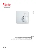
The Room Unit permits temperature
adjustments to be made comfortably
from the heated room.
Settings
There is a mode switch on the front
panel and a dial used for parallel shift
of the weather compensated heating
curve. Inside there is a temperature
sensor.
The dial is used to parallel translate the
weather compensated heating curve.
The flow temperature is raised or lowe-
red respectively by your adjustment.
When the dial is turned all the way
down, the heating circuit is switched off.
Frost protection remains active.
Sensor
The RC21 contains a temperature sensor
which is used by the controller.
The room sensor of RC21 is used to mo-
dify the flow temperature, depending
on the setting of the controller:
The mode switch is designed to change
operating modes of the controller.
In the
Auto Timer
mode the
temperature is controlled
according to the set thermostat
periods.
In the
Continuous Day
mode
the set periods are ignored and
the temperature is controlled
according to the
Day times
settings.
In the
Continuous Night
mode
the temperature is usually set
to lower values. This is a mode
suitable for periods of long ab-
sence, e.g. during holidays.
Installation
Remove carefully the dial from the
housing using a screwdriver. Loosen the
screw beneath. Remove the bright part
of the housing from the black socket.
In order to connect the room unit to a
controller, please use a shielded spiral
cable 4x0.5 or 3x0.5, resp. 4x0.75 or
3x0.75 (e.g. JYTY).
RC 21 is suitable for extra low
voltage only.
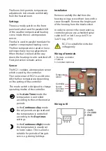
Wiring of terminals
1. Remote controller
2. Sensor
3. Common terminal
Temperature
sensor
Controller
Sensor
Common
terminal
Wiring to IR


