16
HD balance
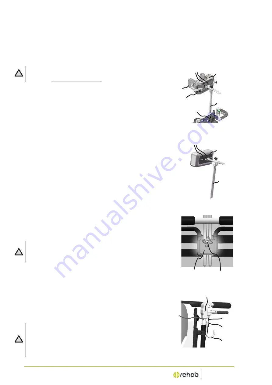
Diagram 33.
Headrest
with lateral supports.
Diagram 35.
Headrest
mount.
Diagram 34.
Neckrest.
4. ACCESSORIES
The following section briefly describes the accessories that are available for the HD Balance. They
are all CE labeled and approved for use with the wheelchair. More information about the respec
-
tive accessories is available as information sheets. Instructions on how accessories are installed
can be found in the respective accessory installation instructions.
- Remember never to use accessories that are not approved for the HD
Balance. The wheelchair is then considered a custom product, read
more in
“2.2. General safety aspects”
.
4.1 Headrest/Neckrest
The headrest (Diagram 33) and each neckrest (Diagram 34)
consists of two parts, one extension tube (1, Diagrams 33 & 34)
and a pillow with a headrest tube (2). The pillow is slightly smaller
on the neckrest than on the headrest.
Set the tube in the bracket (3 in Diagrams 33 & 35) on the rear of
the back by sliding it down through the sleeve to the desired posi-
tion and tighten the knob (7, Diagram 35).
LATERAL ADJUSTMENT:
If necessary, some models of headrests/neckrests can be adjusted
laterally to fit the user’s head position.
- Loosen the screws (6), Diagrams 33 & 34.
- Move the headrest to the desired position and tighten the screws.
The pillow is shaped to provide support at the base of the skull so
that the head can be positioned in a balanced comfortable position.
LATERAL SUPPORT FOR THE HEADREST & NECKREST
Some models of headrests/neckrests can be equipped with one or
two removable lateral supports (4, Diagram 33) to increase lateral
stability. In this case the back of the main headrest is fitted with 2
stand sleeves (5) to adjust the positions of the lateral supports.
- Do not hang things on the headrest/neckrest!
- Some users with special/involuntary movements might risk to get
caught between the rest and the wheelchair. In these cases individual
assessments to decide if rests can be used shall be done.
4.2 Bag hook
The bag hook (1, Diagram 36) is mounted on the operating handle
tube (2) under the operating handle joint (3). The hook is clamped
to the pipe by tightening the screw (4).
On installation and use of the bag hook, ensure that the brake cables
(5) are not damaged.
- A maximum of 5kg may be hung on the bag hook!
- When bags etc. are hung on the bag hook the risk increases of tipping
backwards. How much, depends on the weight and the back-and seat
angle settings.
- It is the responsibility of the carer/user to check the risk of tipping and
make sure the antitip device is used.
Diagram 36.
Bag hook
mounted.
!
!
!
1
2
6
4
5
3
3
7
5
3
1
2
4
1
2
6


