Version 10/21
Page 25 of 49
PAWS UM EN
13.2 Assembly
–
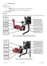
Manual Clamp and Lift
Introduction
This configuration is available in 12”, 14”, 16” and 20” versions. Please check the model number in the model decoder
in Section 9.
The Manual clamps are assembled and adjusted to fit the chair. The Lift is controlled by a lever on the Handlebar and
has three positions
–
Parking, Short and Long Wheelbase.
Procedure
Setting up the device on its legs with Clamps in position.
•
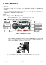
Remove all parts from the packing box and check against Figure 13, below.
Handy Tip:
Keep the carton and packaging for future transport requirements.
Figure 13. Parts shown in the packing box
•
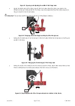
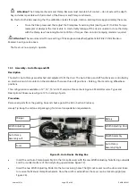
Insert the Manual Clamp Assembly into the Device with the two Width Adjusting Rods and into the two
receiving holes. The QR Lock Levers must be down and loose to receive the Manual Clamp Mechanism.
Once the width is established it is locked upright (see Figure 14).
Figure 14. Assembling the Manual Clamp Assembly to the Width Adjustment Assembly
Width Adjusting Rod
Battery
PAWS Assembly
Manual Clamp
Assembly-Left
Tools
Manual Clamp
Assembly-Right
Width Adjusting
Rod
Charger

