background image

Version 10/21 

Page  28 of 49 

PAWS UM EN 


Attention! 

The tension on this lever can be adjusted using the nut on the other side of the lever. See Figure 11 

above. 


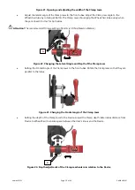
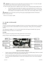
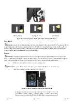
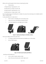
Figure 19. Reversing the Clamp Mechanism Receiver to inward orientation 


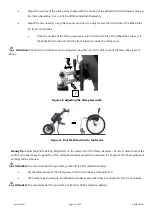
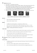
Figure 20. Adjusting the Tension Nut for the Width Adjustment Lever 

(Note the Width Setting Ring on the lower rod) 

Handy Tip:

 Adjust the Width Setting Ring Bolt D on the lower rod of the Clamp Receiver 

 fix this in place to mark the 

width and make it easy to reposition if the Clamping structure needs to be removed for transport. All other 
adjustment settings will be retained. 

 Attention!

 The recommended Torque setting of Bolt D is 5 Nm (Newton Meters). 


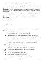
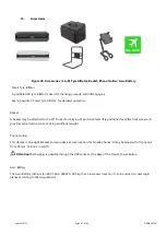
Adjust the jaw opening, to receive the front tube of the Wheelchair. Do this for both sides. 


                                                          Opening                                                     

Adjusting


Summary of Contents for City 12

Page 1: ...Version 10 21 Page 1 of 49 PAWS UM EN Power Assisted Wheelchair Systems PAWS User manual EN City Cruiser and Tourer Series City 12 14 Cruiser 16 Tourer 20 more than mobility...

Page 2: ...nty and Liability 10 Scope of Delivery and Identification 11 Product Specification 12 Configurations Controls and Display 13 Device Assembly 13 1 Naming of Parts 13 2 Assembly Manual Clamp and Lift 13...

Page 3: ...as an auxiliary drive unit for folding and rigid frame wheelchairs Any other use is prohibited Indications The device is indicated for individuals who require power assistance in propelling a Wheelcha...

Page 4: ...equipped Wheelchair or colliding with objects if the Device is not handled or set up correctly Therefore it is very important that a thorough understanding of the use and limitations of the Device is...

Page 5: ...serve and follow the local road traffic regulations in the country of use Practice driving on level ground before attempting sloped surfaces to become familiar with the Device and its limitations When...

Page 6: ...the best way to transport your Battery WARNING The Device and Wheelchair are not designed as a seating option in a moving vehicle e g buses trains metro airplanes etc Do not under any circumstances s...

Page 7: ...for outdoor use in most conditions Best for middle to high speeds across variable terrain Speed Modes 3 5 are only available as a special order upon recommendation by a qualified Distributor that the...

Page 8: ...nts or the battery pack use a dry or slightly damp cloth Never use scouring pads abrasive detergents or aggressive chemicals to clean the components 5 Transport and Storage Transport Please keep the o...

Page 9: ...it a recycling center Attention Do not put the Device in landfill as batteries and other components may leak substances that are hazardous to the environment 7 Maintenance Service Maintenance Despite...

Page 10: ...n and adjust to ensure a firm grip on the Width Adjusting Rods As indicated especially when changing to different chairs Common to both Chair and Device Pneumatic Tyres Tyre pressure check manufacture...

Page 11: ...cturer cannot guarantee proper functioning of the Device in cases of unauthorized service or repair and use of non original parts Regular Servicing will be scheduled with the Distributor at the time o...

Page 12: ...heck motor cable 2 Contact Distributor 12 Error 13 Battery temperature sensor broken 1 Check battery temperature sensor 2 Contact Distributor 13 Error 14 Controller temperature protection value 1 Allo...

Page 13: ...aterials The Battery comes with a 12 month Warranty against manufacturer defect or faulty materials It is a back to base Warranty and is managed via the Distributor It is a limited liability Warranty...

Page 14: ...tes under compressive forces Ensure your wheelchair s frame shape is appropriate o Round Tubing See the CCT o Non round or asymmetrical profile shapes Please consult with your authorised PAWS supplier...

Page 15: ...accessories other than those recommended in this user manual REHASENSE cannot guarantee performance of the PAWS when used with any wheelchairs or chargers other than those recommended in this User Man...

Page 16: ...resulting from inappropriate or incorrect understanding of this User Manual Modifications Any unauthorized modifications of the Device shall void the Warranty If you have any questions concerning mod...

Page 17: ...al packaging materials these may be needed to ship the Device for service or repair Identification The Label located on the side of the main frame contains important information about the Device Figur...

Page 18: ...ISER 16 MANUAL CLAMP LIFT TETRA HANDLES Cruiser Manual Manual 16 RPC16AAS00 PAWS CRUISER 16 AUTOMATIC CLAMP LIFT NORMAL HANDLES Cruiser Auto Auto 16 RPC16AAT00 PAWS CRUISER 16 AUTOMATIC CLAMP LIFT TET...

Page 19: ...dard Standard Turning Radius cm 100 110 120 150 150 Climbing capability dg 10 10 10 10 10 Step climbing height mm 50 50 40 55 55 Range On flat terrain km 40 40 38 35 35 Max Speed km h The gear and spe...

Page 20: ...Device in Park Position Battery Table Dimensions Figure 5 Device and Battery Dimensions Dia Tread Pattern Description Dia Tread Description 12 Brand CHAOYANG Size 12 1 2 x 2 1 4 ETRTO 52 203 Pattern H...

Page 21: ...mping Unclamping Lifting Lowering Driving and Braking Tetra controls to support these actions Tetra Handlebars are for Users with diminished trunk and upper extremity strength and or reduced fine moto...

Page 22: ...cceleration x x 14 Walking Mode Switch Sets to 2 walking speeds x 15 Cruise Button Cruise control on and off x 16 Speed Mode Button Up Selects higher speed modes x 17 Speed Mode Button Down Selects hi...

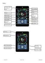
Page 23: ...e Forward Power Consumption Efficiency Walking Mode Driving Status Instant Power Connection between Controller and Screen Traction Mode Instant Speed Driving Mode Total Travel Distance Single Travel T...

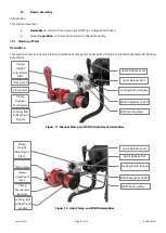
Page 24: ...al and Auto Docking Assemblies Figure 11 Manual Clamp and Width Adjustment Assemblies Figure 12 Auto Clamp and Width Assemblies Quick Release Lever Quick Release Nut Locking Bolt A Angle Width Adjustm...

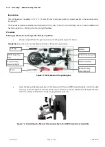
Page 25: ...ve all parts from the packing box and check against Figure 13 below Handy Tip Keep the carton and packaging for future transport requirements Figure 13 Parts shown in the packing box Insert the Manual...

Page 26: ...Legs to the Park position so the Device can stand freely Attention Park is the position required for docking and un docking during the clamping steps Figure 16 Different positions for the Lift Mechani...

Page 27: ...tion of the front chair tubes or where there is a section of straight tube slightly greater than that of the clamping area of the Clamp Jaws Figure 18 Different positions for Height Adjustment Attenti...

Page 28: ...er Note the Width Setting Ring on the lower rod Handy Tip Adjust the Width Setting Ring Bolt D on the lower rod of the Clamp Receiver fix this in place to mark the width and make it easy to reposition...

Page 29: ...nded Torque setting of Bolt A is 50 Nm Newton Meters Figure 22 Changing the Lateral Angle and Depth of the Clamp Jaws Setting the Frontal Angle of the Clamp Jaws to the front tubes Rotate the Clamp Ja...

Page 30: ...to fit the chair The Auto Clamp and Lift functions are controlled by an electronic switch mounted on the Handlebar There are three Lift positions Parking Short and Long Wheelbase positions This config...

Page 31: ...egs to the Park position to allow the device to stand freely Attention Park is the position required for docking and un docking during the clamping steps Figure 28 Different positions for the Lift Mec...

Page 32: ...relation to the chair The fitting height can be adjusted by loosening the Height Adjustment Bolt on the side of the Clamp Mechanism Receiver Measure both sides to ensure equal height settings Height a...

Page 33: ...djusted using the nut on the other side of the lever See Figure 12 above Figure 30 Adjusting the Clamp Jaw width Figure 31 Roll the Wheelchair to the Device Handy Tip Adjust the Width Setting Ring Bol...

Page 34: ...e space between the User s knees and the Device Figure 34 Depth adjustment of the Clamp mechanism in relation to the Device Attention The Clamp mechanism and Clamp Receiver must maintain full contact...

Page 35: ...ion describes the processes for starting up operating and shutting down the Device with the Wheelchair Battery Ensure the Battery is fully charged before a period of extended use Fully charge the Batt...

Page 36: ...will occur automatically in sequence after Clamping there will be a 7 second delay after clamping Driving Positions for Manual Lift Devices Apart from Parking Position 1 on the Indicator there are two...

Page 37: ...ds to be laid down flat for transporting Driving Attention There is a programmed 3 second delay during the setup for added safety when turning on the Device The throttle is inoperative during this del...

Page 38: ...t terrain only We do not recommend climbing inclines in Walk Mode Please change to Mode 1 for inclines Walk Mode may be cancelled by switching off at the Walk Switch applying the driving brakes or eBr...

Page 39: ...sing the Parking Brake button again Safe Driving Always wear a crash helmet and a high visibility vest when using the Device Avoid sudden direction changes and make sharp turns at low speed Be aware o...

Page 40: ...ngage the brakes slowly turn around and go back down the slope Engage obstacles such as kerbs front on or perpendicular to the obstacle to lower the risk of tipping over Always use a low speed when go...

Page 41: ...or carrying of personal items It is positioned over the front wheel and provides extra traction when carrying additional weight Phone Holder This clamps to the Light Bracket and provides a secure loca...

Page 42: ...and abuse of the product Due to transport regulations the Battery Pack is only charged to a maximum of 30 on delivery Make sure the Battery is fully charged before first use Specifications Cells Panas...

Page 43: ...ery Pack Inserting the Battery Pack to power add on Place the bottom of the Battery Pack into the battery holder Gently move the top of the Battery into the Battery Holder Turn the key backward to loc...

Page 44: ...not use Batteries or cells not approved by the manufacturer Please read the Battery handling instructions carefully before use Improper use of the Battery may cause over heating rupture damage or fir...

Page 45: ...nical modifications to the charger It is a high voltage device and tampering could result in high voltage shock and injury For any problems or questions please contact your local Distributor immediate...

Page 46: ...d night light levels Switches control the three modes of Low Beam High Beam and Daytime Driving Light If you turn on the Daytime Driving Light when passing through darkened areas such as tunnels the l...

Page 47: ...essure If you skip Step 4 the target pressure will remain at the previously set value 5 Press the POWER button to start inflating Press again to pause continue The Inflator will stop automatically whe...

Page 48: ...ammable and explosive materials 6 To avoid accidents do not leave the Inflator unattended during operation 7 After long periods of use both the Inflator and Air Tube will be hot Please allow time for...

Page 49: ...AWS UM EN 17 Contact details of the distributor In case of technical questions contact your local Distributor Distributor Aidacare Healthcare Equipment 3A 1 Moorebank Ave Moorebank NSW 2170 T 1300 216...

Reviews: