Version 10/21
Page 30 of 49
PAWS UM EN
Attention!
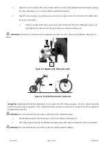
The Clamp mechanism and Clamp Receiver must maintain full contact
–
do not extend the depth
beyond what is possible with full contact of the Receiver and Clamp mechanism.
Do this for both sides ensuring that the calibration marks for angle, rotation and depth are approximately the same.
•
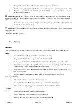
Close the Clamp Jaws and then adjust the Clamp Jaw Tensioning Nut (see Figure 21) to 8 Nm Torque
(example) or whatever the User is able to comfortably manage. If the User is unable to close the clamp
with the Clamp Jaw Tensioning Nut set at 8 Nm of torque, then an Auto Clamping model is required.
Attention!
The recommended Torque setting of this angle and depth adjustment Bolt B is 25 Nm (Newton
Meters). See Figure 24 above.
The Device is now ready to operate.
13.3 Assembly
–
Auto Clamp and Lift
Description
The electric Auto Clamps are attached and adjusted to fit the chair. The Auto Clamp and Lift functions are controlled by
an electronic switch mounted on the Handlebar. There are three Lift positions
–
Parking, Short and Long Wheelbase
positions
This configuration is available in 12”, 14”, 16” and 20” versions. Please check Figure
4. Model Decoder -Types and
Descriptions. Please review Figure 12 for naming of parts.
Procedure
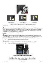
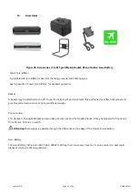
Remove all parts from the packing box and check against the list in Section 9 (above).
Handy Tip: Keep the carton and packaging for future transportation requirements.
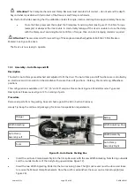
Figure 25. Auto Device Packing Box
•
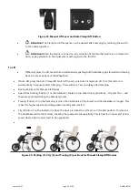
Insert the red Auto Clamp Assembly into the Clamp Receiver with the Jaw Width Adjusting Nuts facing outwards
and the rounded surface of the body facing upwards (see Figure 12).
•
Insert the two Width Adjusting Rods into the two receiving holes. The QR Lock Levers must be down and loose
to receive the Manual Clamp Mechanism. Once the width is established, the Lever can be locked upright (see
Figure 26).
Width Adjusting Rod
Battery
PAWS Assembly
Auto Clamp
Assembly Right
Tools
Auto Clamp
Assembly Left
Width Adjusting
Rod
Charger

