Version 10/21
Page 31 of 49
PAWS UM EN
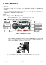
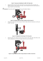
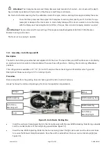
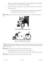
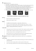
Figure 26. Assembling the Clamp Assembly to the Width Adjustment Assembly
•
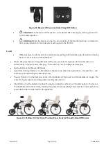
Stand and support the Device on its wheel. Rotate the Support Legs outwards allowing them to support the
Device in a standing position. Ensure the locating bolts at the top of the Supporting Legs are clearly in the key-
way slots.
Figure 27. Rotating the Support Legs to the Park Position
Press the Lift Lock Lever and pull back the Support Legs to the Park position to allow the device to stand freely.
Attention!
“Park” is the position required for docking and un
-docking during the clamping steps.
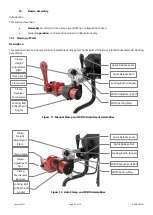
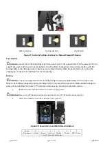
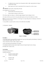
Figure 28. Different positions for the Lift Mechanism
Attention!
There is an Indicator on the Lift Mechanism that shows the position that has been selected. This is
either 1, 2 or 3. For more information on Driving Positions see “Section 1:
Operating
”.
•
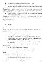
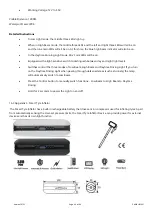
Set the Handlebars. Rotate the handlebars into the correct driving position. Tighten the four hex bolts in the
holding bracket to prevent unwanted movement of the handlebars.
Attention!
The recommended Torque setting for these bolts is 8 Nm (Newton Meters).

