Montageanleitung / instruction sheet / Notice de montage / Istruzioni di montaggio / Instrucciones de montaje
HKV / HKV-D
Stand 02/2009
EDV-Nr. 7002059
Technische Änderungen vorbehalten / subject to technical modification / sous réserve des
modifications techniques / Salvo modifiche tecniche / Salvo modificaciones técnicas
2
GB
INFORMATION. Instructions for use
and important information.
BEWARE! Important information about
function. Failure to heed can impair
function.
Legal information.
Personnel requirements
Prior to starting work, the fitter must read, under-
stand and heed these installation and operating
instructions.
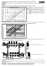
HKV / HKV-D manifolds for underfloor heating
may only be installed, adjusted and maintained
by trained specialists. Trainees may only work on
the product under the supervision of an experi-
enced person. Only if the above instructions
have been adhered to will the manufacturer ac-
cept any liability in line with statutory provisions.
Every instruction contained in these installation
and operating instructions is to be heeded when
using the HKV / HKV-D manifolds.
Correct use
HKV / HKV-D manifolds are used for distributing
and regulating the volume of flow in low tem-
perature underfloor heating systems and under-
floor cooling systems.
HKV / HKV-D manifolds are to be operated using
heating water as per VDI 2035. In the case of
systems, the heating water of which contains
corrosive particles or other contaminants, dirt
traps or filters with a mesh size of no more than
0.8 mm are to be fitted in order to protect the
measuring and control devices.
The max. permissible continuous operating pres-
sure is 6 bar at 80 °C. The max. permissible test
pressure is 8 bar at 20 °C.
Using the manifolds for any purpose other than
that set out in these instructions constitutes im-
proper use. The manufacturer accepts no liability
for damage resulting from improper use of the
manifolds.
For safety and guarantee reasons, no conversion
or modification is permitted.
The manufacturer accepts no liability if connec-
tions and accessories made by other manufac-
turers are used.
Installation / Commissioning
Installation in manifold cabinet:
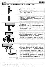
The manifold headers are fitted to the sliding C
profile rails, using the supplied bolts. Please
heed the relevant installation instructions.
Wall installation:
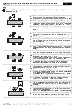
The HKV / HKV-D manifolds are fitted using the
installation kit provided (4 x S 8 rawl plugs and 4
screws 6 x 50)
Hydraulic connections:
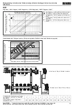
HKV / HKV-D manifolds are supplied with a 1”
ball valve set plus a flush-and-fill unit (SBE).
The manifold headers each have a G 1” male
thread for fitting the ball valve and the flush-and-
fill unit, with flat joints. The union nuts are to be
tightened with an SW 38 ring spanner or open-
ended spanner with approx. 35 - 45 Nm. When
connecting pipes to connections, please see our
pipe installation instructions.
The heating circuits for the individual rooms are
labelled with the self-adhesive labels provided.
These can be stuck to the manifold itself.
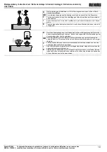
Flushing and filling the heating circuits:
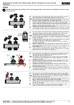
Hoses with 3/4” connections tubes are screwed
to the hose of the feed taps to fill the heating cir-
cuit manifold. Slowly open and close the valves
connections to operate the flush-and-fill unit.
Beware!
During the filling and flushing process, the 1” ball
valves on the flow and return headers must re-
main closed, otherwise the high water pressure
might damage the heating system or might acti-
vate the safety valve.
Only fill and flush the manifold in the direction of
flow! Please avoid high differential pressure (> 1
bar) and pressure shocks.


