background image

2

BEDIENUNGS- UND WARTUNGSANLEITUNG

 - Inhaltsverzeichnis

TAE K15÷K20

Die Angaben im vorliegenden Handbuch sind nicht bindend und können ohne vorherige Benachrichtigung vom Hersteller geändert werden. 

Nachdruck - wenn auch nur teilweise - verboten.

7.9

Am Display angezeigte Werte..................................................................................................18

7.10  Ein- und Ausschalten der Einheit............................................................................................18
7.11 Einstellung der Einheit auf Standby.........................................................................................18
7.12 Das Menü Funktionen: Taste “

!

” ..........................................................................................19

7.12.1 Zugriff auf das Menü Funktionen .............................................................................................................19
7.12.2 Ausgang aus dem Menü Funktionen  ........................................................................................................19
7.12.3 Ansicht der Alarme “ALrM” ....................................................................................................................19
7.12.4 Rückstellung eines Alarms “rSt”  .............................................................................................................19
7.12.5 Ansicht der Alarmhistorik “ALoG”  .........................................................................................................19
7.12.6  Löschen der Alarmhistorik “ArSt”  .........................................................................................................19
7.12.7 Ansicht der Betriebsstunden der Lasten “C1Hr - C2Hr - PFHr”  ...........................................................20

7.13 Sonstige Funktionen über Tastatur...........................................................................................20

7.13.1 Ansicht des Setpoints ................................................................................................................................20
7.13.2 Änderung des Setpoints  ............................................................................................................................20

7.14 Sondelegende ...........................................................................................................................20

E

INSTELLUNG


DER

 K

OMPONENTEN

.............................................................................................................21

8.1

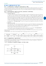
Integralschutz des Kompressors (PI)........................................................................................21

8.2

Kältemittel-Hoch- und Niederdruckschalter ............................................................................21

8.3

Funktionsweise der Verdichter.................................................................................................21

8.3.1 Schaubild der Regelung der Verdichter in Kühlung  ................................................................................21

B

ETRIEB


UND

 W

ARTUNG

..............................................................................................................................22

9.1

Betrieb ......................................................................................................................................22

9.2

Wartung....................................................................................................................................22

9.3

.Zugang zur Maschine ..............................................................................................................22

9.4

Programmierung der Kontrollen und der Wartung ..................................................................23

F

EHLERSUCHE

...............................................................................................................................................24

E

INSTELLUNGSTABELLEN

.............................................................................................................................27

11.1 Einstellungen der Parameter.....................................................................................................27

11.1.1 Temperaturregelparameter ......................................................................................................................27
11.1.2 Konfigurationsparameter .........................................................................................................................27
11.1.3 Dynamischer Setpoint-Parameter  (KEINE AKTIVE FUNKTION)  ........................................................28
11.1.4 Energy-Saving Parameter (KEINE AKTIVE FUNKTION)  .....................................................................28
11.1.5 Kompressorparameter ..............................................................................................................................28
11.1.6 Ventilatorparameter .................................................................................................................................28
11.1.7 Parameter Heizelement Frostschutz / Hilfsboiler ....................................................................................28
11.1.8 Abtauparameter (KEINE AKTIVE FUNKTION)  .....................................................................................28
11.1.9 Alarmparameter .......................................................................................................................................29
11.1.10Laserparameter (KEINE AKTIVE FUNKTION) .....................................................................................29

A

LARME

.........................................................................................................................................................30

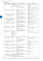
12.1 Alarmcodes und ausgeführte Handlungen ...............................................................................30
12.2 Tabelle: Sperre der Ausgänge ..................................................................................................33

Summary of Contents for TAE K15

Page 1: ...38171300180_010 TAE K15 K20 WATER CHILLERS OPERATING AND MAINTENANCE MANUAL WASSERKÜHLER BEDIENUNGS UND WARTUNGSANLEITUNG ...

Page 2: ......

Page 3: ... Dimensions 8 3 1 2 Characteristics of pumps 8 DESCRIPTION 9 4 1 Components 9 4 2 Cooling circuit 9 4 3 Compressors 9 4 4 Condenser 9 4 5 Evaporator 9 4 6 Tank 9 4 7 Pump 10 4 8 Fans 10 4 9 Casing 10 4 10 Materials in contact with the liquid to be cooled 10 4 11 Minimum distances from walls in the installation ambient 10 4 12 Electrical circuit 10 INSTALLATION 11 5 1 Inspection 11 5 2 Positioning ...

Page 4: ...by keyboard 20 7 13 1 How to display the Set Point 20 7 13 2 How to modify the Set Point 20 7 14 Probe key 20 OTHER COMPONENTS SETTING 21 8 1 Compressor integral protection PI 21 8 2 Refrigerant high and low pressure switches 21 8 3 Compressor operation 21 8 3 1 Compressor regulation graphic in Chiller mode 21 OPERATION AND MAINTENANCE 22 9 1 Operation 22 9 2 Maintenance 22 9 3 Unit access 22 9 4 ...

Page 5: ... meaning is the following 1 1 H o w t o i n t e r p r e t t h e m o d e l TAE K15 Refrigerator with tank Tank air cooled condenser three phase power supply and 1 5 hp indicative power hermetic compressor TAE K20 Refrigerator with tank Tank air cooled condenser three phase power supply and 2 0 hp indicative power hermetic compressor ATTENTION This manual provides the user installer and maintenance ...

Page 6: ... unsafe and that there is no risk to persons or property Any improper use of the machine will relieve the manufacturer from any liability for possible personal injury or property damage Arbitrary modifications made to the unit will automatically invalidate all forms of guarantee provided by the manufacturer ATTENTION The hot cold water produced by MTA units cannot be used directly for domestic hyg...

Page 7: ...onditions which should be corrected ATTENTION Use only refrigerant gas specified on the specification plate of the unit Make sure that all instructions concerning operation and maintenance are strictly followed and that the complete unit with all accessories and safety devices is kept in good working order The accuracy of pressure and temperature gauges must be regularly checked They must be renew...

Page 8: ...ediately with plenty of water Remove contaminated clothing immediately FIRE FIGHTING MEASURES Means of extinction Any means Specific dangers Pressure increase Specific methods Cool the containers with water sprays MEASURES IN THE EVENT OF ACCIDENTAL LEAKAGE Individual precautions Evacuate personnel to safe areas Provide adequate ventilation Use means of personal protection Environmental precaution...

Page 9: ...y alkaline metals granulated metals salts Al Zn Be etc in powder Hazardous decomposition products Halogen acids traces of carbonyl halides TOXICOLOGICAL INFORMATION Acute toxicity ALC inhalation 4 hours lab rats 567 ml l Local effects Concentrations substantially above 1000 ppm v v can cause narcotic effects Inhalation of products in decomposition can lead to respiratory difficulty pulmonary oedem...

Page 10: ... current consumed by the unit during the limit working conditions INSTALLED POWER P max It is the power absorbed by the unit during the limit working conditions PROTECTION As defined by the EN 60529 European standard REFRIGERANT This is the refrigerant fluid in the unit REFRIGERANT QUANTITY This is the quantity of refrigerant fluid contained in the unit MAX COOLING PRESSURE This is the design pres...

Page 11: ...ng of copper tubes and collectors aluminium fins and shoulders in galvanised sheet 4 5 E v a p o r a t o r The evaporator is a finned pack type the water flows in contact with the finned surface and at a speed that guarantees low pressure drops while the refrigerant fluid flows inside the tubes A plate exchanger can be fitted as an alternative In the TAE K15 K20 models the exchanger is protected a...

Page 12: ...ith a superior support to the fan safety protection grill 4 9 C a s i n g The base uprights and panels are made of galvanized carbon steel and held together by screws and or rivets All panels undergo a phosphor degreasing process followed by epoxy polyester powder coating The frame is designed to allow easy access to all machine components 4 1 0 M a t e r i a l s i n c o n t a c t w i t h t h e l ...

Page 13: ...mperature is above 0 C it is possible for the machine during stoppages in the cold seasons to find itself in an environment with a temperature below 0 C In these cases if the machine is not emptied antifreeze ethylene glycol must be added in the following percentages to prevent the formation of ice Add the following anti freeze ethylene glycol percentages in order to avoid freezing when operating ...

Page 14: ... inlet pipe to avoid the entry of solid particles that could damage the pumps The non observance of this instruction can cause big damages to the evaporator TAE unit model 015 020 Evaporator water IN OUT connections Rp 3 4 Process water inlet Process water outlet When filling the circuit with liquid check to ensure the absence of air bubbles and contaminants If the pump runs noisily or emits anoma...

Page 15: ...on of the power supply in the event of insulation failure protection against indirect contacts in compliance with IEC 364 by means of a differential device normally with operation nominal current of 0 03 A 3 at the beginning of the electrical supply cable must be guaranteed a protection against direct contacts with a protection degree of IP2X or IPXXB at least 4 at the beginning of the electrical ...

Page 16: ...tion is correct If necessary invert two phases of supply 12 Check that the pressure difference between the value read on the manometer located on the machine control panel with the pump in motion and the value read with the pump stopped is higher than the available pressure with the pump s maximum flow capacity If this difference is lower it means that the water flow capacity is higher than the ma...

Page 17: ...gnalling icons ICON MEANING ICON MEANING Celsius degrees If displayed Low pressure alarm Fahrenheit degrees If not displayed Antifreeze resistance Bar Psi Pump on Compressor 1 Flow meter alarm Compressor 2 Time to defrost starting Stand by unit Fans on General alarm 0 Indication for Function Menu entering 1 High pressure alarm BUTTON FUNCTION 2 It selects water temperature and ambient air temperat...

Page 18: ...s they allow to start a manual defrosting cycle function not present LED LED STATUS MEANING LED LED STATUS MEANING 6 Not enabled 7 Not enabled Steady Unit on in chiller modality 7 Not enabled 7 Flashing Programming phase if flashes together with led Clock adjustment 7 Not enabled BUTTON FUNCTION 8 It allows to enter Function Menu 9 If pressed for 5 sec it allows to display or modify the set point ...

Page 19: ...t flashing in the top of the display appears ALL the first group of parameters 2 Select the various groups using and buttons 3 After selecting a group press 4 button if the selected group is part of the selected menu or any parameter of this group has been moved in this menu in the bottom of the display it appears the Label and the code of the group s first parameter present in Pr1 its value appea...

Page 20: ...ting differential Parameter CF42 CF44 0 In the bottom part of the display it appears the probe BEWOT Parameter CF42 CF44 1 In the bottom part of the display it appears the probe BTWOT Parameter CF42 CF44 2 In the bottom part of the display it appears the probe PCP1 Parameter CF42 CF44 3 In the bottom part of the display it appears the probe BAT1 Parameter CF42 CF44 4 In the bottom part of the disp...

Page 21: ...top of the display it appears the Label rSt it the alarm can not be reset it appears the Label NO 5 Use or button to scroll all the alarms 6 When the Label rSt is displayed press 4 to reset the alarm and go to the following one 7 To exit press button or wait for time out 30 seconds 7 12 5 How to display the alarm historic ALoG 1 Press button to enter Function menu 2 Use or button to select the fun...

Page 22: ...Hr and the operating hours appear in the top of the display 3 Press 4 button for 3 seconds in the top of the display it will appear 0 It indicates that the reset has happened 4 To exit Function menu press button or wait for time out 15 seconds 5 For the other loads repeat the operations from point 2 to point 4 7 1 3 O t h e r f u n c t i o n s b y k e y b o a r d 7 13 1 How to display the Set Poin...

Page 23: ...pressor intake pressure increases and exceeds the pressure switch tripping value it will restart It will be possible to start up the unit again following the alarm reset procedure described in Chapter 7 Electronic Board If the cause of the pressure switch tripping has not removed this cycle will repeat continuously 2 high pressure switch HP This monitors the refrigerant compressor discharge pressu...

Page 24: ...ff automatically when the preset water outlet temperature has been reached 9 2 M a i n t e n a n c e ATTENTION Before proceeding with the installation or the maintenance of these units be sure that all personnel concerned have read and understood the Chapter 2 Safety 9 3 U n i t a c c e s s ATTENTION Everytime the panels must be removed the unit must be switched off and disconnected from power sup...

Page 25: ...in expected limits and in particular that it is not lower than the value corresponding to the maximum flow capacity x Clean the water filter We recommend to clean the filter after a week from the unit starting x Check that the liquid indicator if present is full or with a small stream of bubbles when the compressor is running x Check that the unit current absorption is within the values on the dat...

Page 26: ...he outlet temperature BTWOT see A1 1 with pump installed on the machine pressure difference read on the machine pressure gauge too low with pump stopped and pump running possible tripping of pump thermal protection Reduce water flow to within the preset limits for example by closing partially a pump outlet cock Reset the pump thermal protection and check the electrical absorption B2 See point C B2...

Page 27: ... star up the unit again chapter Electronic Board D5 See A4 D5 1 See D1 1 Clean the front surface of the condenser Follow the alarm reset procedure to star up the unit again chapter Electronic Board D6 Thermal load too high D6 1 Water outlet temperature too high refrigerant compressor stops main alarm relay tripped If possible reduce the thermal load to within the design limits Follow the alarm res...

Page 28: ...2 1 See problem the compressor stops and restarts main alarm relay tripped Increase the water flow J Alarm displayed A08 pump thermal protection J1 The pump s thermal protection device has tripped because the water flow is too high J1 1 See problem main alarm relay tripped the refrigerant compressor and pump stop the indication A08 appears on the display alternated to BTWOT value the pressure diff...

Page 29: ...r level and Chapter 7 How to modify a parameter s value 11 1 1 Thermoregulation parameters 11 1 2 Configuration parameters Parameter Level Description Min Max Udm Resolution Factory setting ST01 U Summer set point ST05 ST06 C F C F Dec Int 9 C with 1 compr 48 F with 1compr 8 C with 2 compr 47 F with 2compr ST02 U Summer differential 00 0 00 0 25 0 45 0 C F C F Dec Int 4 C with 1 compr 7 F with 1 c...

Page 30: ... Pr2 Password 0 999 Parameter Level Description Min Max Udm Resolution Factory setting Pr2 Password 0 999 Parameter Level Description Min Max Udm Resolution Factory setting Pr2 Password 0 999 Parameter Level Description Min Max Udm Resolution Factory setting EVAPORATOR UNLOADING CONDENSER UNLOADING Pr2 Password 000 999 Parameter Level Description Min Max Udm Resolution Factory setting HOT START Pr...

Page 31: ...an thermal protection Digital input enabled open collector outlet alarm relay is activated The buzzer is activated The icon for general alarm flashes The alarm code is displayed Manual Digital input disabled and the resetting procedure is carried out A02 Low pressure switch alarm Digital input low pressure switch enabled open collector outlet alarm relay is activated The buzzer is activated The ic...

Page 32: ...s activated The icon for general alarm flashes The alarm code is displayed Manual Digital input disabled and the resetting procedure is carried out A10 Compressor 2 thermal alarm Digital input enabled open collector outlet alarm relay is activated The buzzer is activated The icon for general alarm flashes The alarm code is displayed Manual Digital input disabled and the resetting procedure is carr...

Page 33: ...mutation valve not configured open collector outlet alarm relay is activated The buzzer is activated The icon for general alarm flashes The alarm code is displayed Automatic With correct re programming ACF3 Configuration alarm Two digital inputs with the same configuration open collector outlet alarm relay is activated The buzzer is activated The icon for general alarm flashes The alarm code is di...

Page 34: ...t unit outlet Yes Yes Yes A05 High temperature High pressure Yes Yes A06 Low pressure Low temperature Yes Yes A07 Analogue input antifreeze Yes Yes A07 Digital input antifreeze Yes Yes A07 Motorcondensing antifreeze Yes Yes A08 Flow meter pump thermal protection Yes Yes Boiler Res Yes Yes A09 Compressor 1 thermal protection Yes A10 Compressor 2 thermal protection Yes A09 A10 Compressor 1 2 thermal...

Page 35: ...umpen 8 BESCHREIBUNG 9 4 1 Komponenten 9 4 2 Kompressoren 9 4 3 Kondensator 9 4 4 Verdampfer 9 4 5 Speicher 9 4 6 Pumpen 10 4 7 Ventilatoren 10 4 8 Gehäuse 10 4 9 Materialien die mit der zu kühlenden Flüssigkeit in Berührung sind 10 4 10 Mindestabstände von den Wänden des Installationsraumes 10 4 11 Elektrischer Kreislauf 10 INSTALLATION 11 5 1 Kontrolle 11 5 2 Aufstellung 11 5 3 Frostschutz 11 5 ...

Page 36: ...erung des Setpoints 20 7 14 Sondelegende 20 EINSTELLUNG DER KOMPONENTEN 21 8 1 Integralschutz des Kompressors PI 21 8 2 Kältemittel Hoch und Niederdruckschalter 21 8 3 Funktionsweise der Verdichter 21 8 3 1 Schaubild der Regelung der Verdichter in Kühlung 21 BETRIEB UND WARTUNG 22 9 1 Betrieb 22 9 2 Wartung 22 9 3 Zugang zur Maschine 22 9 4 Programmierung der Kontrollen und der Wartung 23 FEHLERSU...

Page 37: ... 1 1 E r k l ä r u n g d e r M o d e l l b e z e i c h n u n g TAE K15 Kühler mit Tank und Kondensator luftgekühlt mit dreiphasiger Stromversorgung mit hermetischem Kompressor von 1 5 PS Richtleistung TAE K20 Kühler mit Tank und Kondensator luftgekühlt mit dreiphasiger Stromversorgung mit hermetischem Kompressor von 2 0 PS Richtleistung ACHTUNG Diese Betriebsanleitung enthält alle technischen Info...

Page 38: ...inrichtungen nicht beschädigt oder unsicher werden und dass keine Gefahren für Personen oder Sachen entstehen Ein unkorrektes Verhalten und eine unkorrekte Bedienung der Einheit seitens des Benutzers befreien den Hersteller von jeglicher Haftung für mögliche Schäden und oder Unfälle An der Maschine durchgeführte willkürliche Änderungen führen zum Verfall jeglicher Garantieleistung durch den Herste...

Page 39: ...allgemein anerkannte Lagermethoden welche im Einklang mit den Umweltvorschriften stehen angewendet werden Es müssen schriftliche Aufzeichnungen über alle an der Anlage und den Zusatzeinrichtungen durchgeführten Arbeiten gemacht werden Häufig wiederkehrende Reparaturarbeiten können ein Hinweis auf ungünstige Arbeitsbedingungen sein Es müssen dann optimale Bedingungen geschaffen werden ACHTUNG Es da...

Page 40: ...mittel muß gemäß der Vorschriften der Hersteller sowie gemäß der gesetzlichen und Sicherheitsvorschriften am Aufstellungsort erfolgen 2 7 1 Kältemittel Sicherheitsdatenblatt R134a Bezeichnung R134a 1 1 1 2 Tetrafluorethan GEFAHRENHINWEISE Hauptgefahren Ersticken Spezifische Gefahren Nicht bekannt ERSTE HILFE MAßNAHMEN Allgemeine Informationen Bewusstlosen Personen nichts verabreichen Einatmen Ins ...

Page 41: ...löslichkeit 0 15 an Gewicht bei 25 C und atmosph Druck STABILITÄT UND REAKTIONEN Stabilität keine Reaktion wenn nach den vorgesehenen Anweisungen angewendet Zu vermeidende Stoffe Alkalimetalle Erdalkalimetalle granulierte Metallsalze Al Zn Be usw in Pulverform Gefährliche Zersetzungsprodukte Halogensäuren Spuren von Halogenkarbonat TOXIKOLOGISCHE INFORMATIONEN Akute Vergiftung ALC Einatmung 4 Stun...

Page 42: ...Merkmale der Stromversorgung MAX STROMAUFNAHME I max Stromaufnahme der Maschine in den Einsatzgrenzen INSTALLIERTE LEISTUNG P max Leistungsaufnahme der Maschine in den Einsatzgrenzen SCHUTZART Gemäß Europanorm EN 60529 KÄLTEMITTEL Kältemittel mit dem die Maschine gefüllt wurde KÄLTEMITTELBEFÜLLUNG Befüllmenge des Kältemittels in der Anlage MAX DRUCK KÄLTEKREISLAUF Druck des Kältekreislaufs nach Pr...

Page 43: ...und die Lamellen aus Aluminium Das Trägergestell besteht aus Zinkblech 4 4 V e r d a m p f e r Der Verdampfer verfügt über ein Lamellenpaket mit Kupferrohren und Alulamellen das Wasser umströmt die Lamellenfläche mit einer solchen Geschwindigkeit dass geringe Druckverluste garantiert sind wogegen das Kältemittel in den Rohren fließt Andernfalls kann ein Plattenverdampfer montiert sein An den Model...

Page 44: ...hutzart der Ventilatoren ist IP44 Alle Ventilatoren sind Klasse F isoliert und damit für Außenbetrieb unter jeder Wetterbedingung geeignet Die Montage vervollständigt ein Unfallschutzgitter an der Oberseite als Halterung des Ventilators 4 8 G e h ä u s e Das gesamte Untergestell die Ständer sowie die Paneele sind aus verzinktem Kohlenstahlblech hergestellt und miteinander mit Schrauben und oder Ni...

Page 45: ...i Stillstand während der kalten Jahreszeit Umgebungstemperaturen unter 0 C ausgesetzt sein kann Entweder muß sie dann entleert werden oder der Wasserkreislauf muß mit einem entsprechenden Prozentsatz Frostschutzmittel Äthylenglykol versehen werden Um Eisbildung bei niederen Wasserauslauftemperaturen zu verhindern ist der nachfolgend aufgeführte Frostschutz vorzusehen 5 4 W a s s e r a n s c h l ü ...

Page 46: ...len um das Eindringen von Festteilchen und somit eine Beschädigung der Pumpen zu vermeiden Die Nichtbeachtung dieser Vorschrift kann unreparierbare Schäden an Verdampfer verursachen Modell TAE K15 K20 Verdampferwasseranschlüsse IN OUT Rp 3 4 Prozesswassereintritt Prozesswasseaustritt Wenn man den Kreislauf mit der Flüssigkeit füllt ist sicher zu stellen dass keine Luftblasen oder Schmutzteilchen v...

Page 47: ...äß IEC346 Schutz gegen indirekte Kontakte gemäß den Vorschriften der Norm IEC 364 mittels einer Differentialstromvorrichtung gesorgt werden gewöhnlich mit Auslösestrom von 0 03 A 3 Am Anfang des Anschlusskabels muß für eine Berührungsschutz gesorgt werden Mindestschutzart IP2X oder IPXXB 4 Die Zuspeisung muß gemäß den Informationen des Schaltplans gegen Überstrom abgesichert werden 5 Kabelquerschn...

Page 48: ...rekt funktioniert er darf nicht laut werden oder sich überhitzen weiterhin prüfen ob der Drehsinn den Ventilatoren und der Pumpe falls vorhanden korrekt ist Falls erforderlich zwei Phasen der Stromversorgung umkehren 12 Prüfen dass die auf dem Manometer am Bedienpult der Einheit abgelesene Druckdifferenz zwischen laufender und stehender Pumpe höher ist als die bei maximaler Förderleistung der Pump...

Page 49: ...Kapitel 7 9 Am Display angezeigte Werte Bereich rechts Symbole SYMBOL BEDEUTUNG SYMBOL BEDEUTUNG Celsius Grade falls angezeigt Unterdruckalarm Fahrenheit Grade falls nicht angezeigt Frostschutzheizelement Bar Psi Pumpe aktiviert Kompressor 1 Strömungswächteralarm Kompressor 2 Zeit bis zum Abtaubeginn Uhrzeit Einheit auf Standby Ventilator aktiviert Sammelalarm 0 Zeigt den Zugriff auf das Menü Funk...

Page 50: ...llen Abtauzykluss KEINE AKTIVE FUNKTION LED STATUS DER LED BEDEUTUNG LED STATUS DER LED BEDEUTUNG 6 keine aktive Funktion 7 keine aktive Funktion Leuchtet Einheit eingeschaltet als Chiller 7 keine aktive Funktion 7 Blinkt Programmierungsphase blinkt zusammen mit LED Einstellung der Uhr 7 keine aktive Funktion TASTE FUNKTION 8 Zugriff auf das Menü Funktionen und Einstellung der Uhr 9 Falls 5 Sekund...

Page 51: ...ngliche Parametermenü Pr1 1 Ein paar Sekunden auf die Tasten 4 drücken 7 und beginnen zu blinken Am oberen Display wird ALL angezeigt die erste Parameterfamilie 2 Die verschiedenen Familien mit den Tasten und auswählen 3 Nach der Auswahl der Familie und Druck auf Taste 4 wird das Instrument falls die gewählte Parameterfamilie Teil des gewählten Menüs ist oder ein Parameter dieser Familie in das Me...

Page 52: ...l angezeigt Parameter CF42 CF44 0 Am unteren Display wird als Standard die Sonde BEWOT angezeigt Parameter CF42 CF44 1 Am unteren Display wird als Standard die Sonde BTWOT angezeigt Parameter CF42 CF44 2 Am unteren Display wird als Standard die Sonde BCP1 angezeigt Parameter CF42 CF44 3 Am unteren Display wird als Standard die Sonde BAT1 angezeigt Parameter CF42 CF44 4 Am unteren Display wird der ...

Page 53: ... Taste 4 drücken am unteren Display wird der Alarmcode angezeigt 4 Falls es sich um einen rückstellbaren Alarm handelt erscheint im oberen Displayteil das Label rSt falls der Alarm nicht rückstellbar ist erscheint das Label NO 5 Mit den Tasten oder alle Alarme durchlesen 6 Auf 4 an Label rSt drücken um den Alarm rückzustellen und auf den nächsten überzugehen 7 Zum Beenden auf Taste drücken oder da...

Page 54: ...ur Einheiten 201 351 PFHr am oberen Display werden die Betriebsstunden angezeigt 3 3 Sekunden lang auf Taste 4 drücken am oberen Display wird 0 angezeigt Nullstellung erfolgt 4 Das Menü Funktionen durch Druck auf Taste verlassen oder warten bis die Timeout Zeit abgelaufen ist 15 Sekunden 5 Die Vorgänge von Punkt 2 bis Punkt 4 für die anderen Lasten wiederhole 7 1 3 S o n s t i g e F u n k t i o n ...

Page 55: ...r automatisch zurück Entsprechend der Anweisung im Kapitel 7 Elektronische Steuerzentrale kann die Anlage nach Alarmreset wieder gestartet werden Wurde die Ursache des Alarms jedoch nicht beseitigt erfolgt erneut ein Auslösen des Druckschalters 2 Hochdruckschalter HP Der Hochdruckschalter kontrolliert den Druck im Auslas des Kältekompressors und verhindert dass der Druck auf Werte ansteigt die für...

Page 56: ...n da dies bei Erreichen der eingestellten Temperaturen automatisch erfolgt 9 2 W a r t u n g ACHTUNG Vor Installation oder Wartung der Anlage muß sichergestellt sein dass das betreffende Personal das Kapitel 2 Sicherheit 9 3 Z u g a n g z u r M a s c h i n e ACHTUNG Eingriffe zu denen die Öffnung der Paneele notwendig ist dürfen nur mit ausgeschalteter und vom Stromnetz abgetrennter Einheit ausgef...

Page 57: ...derleistung entspricht x Wasserfilter reinigen Die Reinigung des Filters wird eine Woche nach dem ersten Anlassen der Anlage empfohlen x Das Flüssigkeitsschauglas prüfen falls vorhanden Es muss bei laufendem Kompressor voll sein oder darf nur wenige Blasen zeigen x Die Stromaufnahme prüfen sie muss innerhalb der Kenndaten sein x Den Kältemittelkreislauf untersuchen um den Zustand der Leitungen zu ...

Page 58: ...wohl bei stehender als laufender Pumpe Auslösung des Wärmeschalters der Pumpe Wasserdurchfluss eindrosseln am Auslas der Pumpe bis richtiger Wert erreicht wird z B durch teilweises Schließen des Hahns Wärmeschalter der Pumpe rückstellen und elektrische Aufnahmewerte kontrollieren B2 Siehe Punkt C Bevor Eisbildung am Verdampfer die Anlage stoppt erhöht sich der Druckabfall B2 1 Siehe Punkt C Siehe ...

Page 59: ...r zu hoch Kältekompressor schaltet aus Sammelstörmeldung Belastung auf Auslegungswert zurückbringen Alarme rückstellen um die Anlage wieder einzuschalten siehe Elektronische Steuerzentrale E Niederdruckschalter LP löst aus Alarmanzeige A02 E1 Kältemittelmangel siehe auch A5 E1 1 Kompressor stoppt Anzeige A02 erscheint am Display abwechselnd zur Temperaturanzeige von BTWOT Sammelstörmeldung die LED...

Page 60: ... und Pumpe ausgeschaltet Am Display erscheint A08 abwechselnd mit dem von BTWOT Der Differenzdruck am Manometer bei laufender oder stehender Pumpe ist niedriger als der verfügbare Pumpendruck Auslöser zurückstellen Druck im Wasserkreis erhöhen indem z B ein Absperrhahn im Pumpenauslass gedrosselt wird J2 Kühlluftgitter vom Pumpenmotor verstopft J2 1 Siehe Problem Sammelstörmeldung Kältekompressor ...

Page 61: ... Pr1 USER und Kapitel 7 Änderung des Wertes eines Parameters vorgehen 11 1 1 Temperaturregelparameter 11 1 2 Konfigurationsparameter Parameter Niveau Beschreibung Min Max Udm Auflösung Fabrikwert ST01 U Setpoint Sommerbetrieb ST05 ST06 C F Dec Int 9 C mit 1 Kompr 48 F mit 1 Kompr 8 C mit 2 Kompr 47 F mit 2 Kompr ST02 U Differential Sommerbetrieb 00 0 00 0 25 0 45 0 C F Dec Int 4 C mit 1 Kompr 7 F ...

Page 62: ...oint der Einheit 5 Status der Einheit 6 Set Laser 7 Nichts 8 Betriebsdifferential 0 6 4 Pr2 Passwort 0 999 Parameter Niveau Beschreibung Min Max Udm Auflösung Fabrikwert Pr2 Passwort 0 999 Parameter Niveau Beschreibung Min Max Udm Auflösung Fabrikwert Pr2 Passwort 0 999 Parameter Niveau Beschreibung Min Max Udm Auflösung Fabrikwert UNLOADING VERDAMPFER UNLOADING KONDENSATOR Pr2 Passwort 000 999 Pa...

Page 63: ...önnen ohne vorherige Benachrichtigung vom Hersteller geändert werden Nachdruck wenn auch nur teilweise verboten 11 1 9 Alarmparameter 11 1 10 Laserparameter KEINE AKTIVE FUNKTION Parameter Niveau Beschreibung Min Max Udm Auflösung Fabrikwert Pr2 Passwort 0 999 Parameter Niveau Beschreibung Min Max Udm Auflösung Fabrikwert Pr2 Passwort 0 999 ...

Page 64: ... Verfahren Alarm Kondensventilator Aktivierung des digitalen Eingangs Aktiviert Ausgang Open Collector Alarmrelais aktiviert Alarmsummer Anzeige des Codes am Display Manuell Deaktivierung digitaler Eingang nicht aktiv plus Reset Verfahren A02 Alarm Unterdruckschalter Aktivierung des digitalen Eingangs des Unterdruckschalters Aktiviert Ausgang Open Collector Alarmrelais aktiviert Alarmsummer Blinke...

Page 65: ... Auslösungen Stunde Manuell Deaktivierung digitaler Eingang nicht aktiv für eingestellt Zeit plus Reset Verfahren A09 Alarm Wärmeschutz Kompressor 1 Aktivierung des digitalen Eingangs Aktiviert Ausgang Open Collector Alarmrelais aktiviert Alarmsummer Blinken des Symbols für Sammelalarm Anzeige des Codes am Display Manuell Deaktivierung digitaler Eingang nicht aktiv plus Reset Verfahren A10 Alarm W...

Page 66: ... Manuell Reset Verfahren Falls der Alarm nach dem Reset wieder auftritt bleibt die Vorrichtung blockiert ACF2 Konfigurations alarm Verflüssigungskontr olle Sonde nicht konfiguriert Aktiviert Ausgang Open Collector Alarmrelais aktiviert Alarmsummer Blinken des Symbols für Sammelalarm Anzeige des Codes am Display Automatisch Mit korrekter Neuprogrammierung ACF3 Konfigurations alarm Zwei digitale Ein...

Page 67: ...atur A04 Niedrige Lufttemperatur am Austritt aus der Maschine Ja Ja Ja A05 Übertemperatur Hochdruck Ja Ja A06 Unterdruck Untertemperatur Ja Ja A07 Frostschutz analogischer Eingang Ja Ja A07 Frostschutz digitaler Eingang Ja Ja A07 Frostschutz Verdichter Verflüssigereinheiten Ja Ja A08 Strömungswächter Ja Ja Heizel Boiler Ja Ja A09 Wärmeschutz Kompressor 1 Ja A10 Wärmeschutz Kompressor 2 Ja A09 A10 ...

Page 68: ...WARTUNGSANLEITUNG Kapitel 12 Alarme TAE K15 K20 Die Angaben im vorliegenden Handbuch sind nicht bindend und können ohne vorherige Benachrichtigung vom Hersteller geändert werden Nachdruck wenn auch nur teilweise verboten ...

Page 69: ...A 003 D min L min D min mm L min mm D min mm L min mm 630 750 320 690 ...

Reviews: