3
OPERATING AND MAINTENANCE MANUAL
Chapter 1 - General Information
TAE K15÷K20
The data in this manual are not binding and may be changed by the manufacturer without notice.
Reproduction of this manual, even partial, is strictly prohibited.
C
HAPTER
1
G
ENERAL
I
NFORMATION
The machines described in this manual are called “WATER CHILLERS”.
This manual is written for those responsible for the installation, use and maintenance of the unit.
The components used are of high quality and all the projecting process, from the production to the unit checking, has been manufactured in
conformity with ISO 9001 norms.
In most applications, the liquid of the user circuit is water and the term “WATER” will be used even if the liquid of the user circuit is different
from water (e.g. a mixture of water and glycol).
Here below the term “PRESSURE” will be used to indicate the gauge pressure.
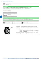
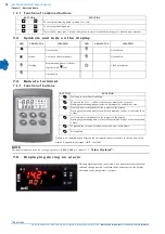
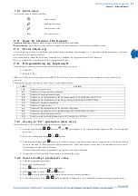
The following symbols are shown on the stickers on the unit as well as on the overall dimension drawing and refrigeration circuits in this manual.
Their meaning is the following:
1 . 1
H o w t o i n t e r p r e t t h e m o d e l
TAE K15:
Refrigerator with tank (Tank), air-cooled condenser, three-phase power supply and
1,5
hp (indicative power) hermetic compressor.
TAE K20
: Refrigerator with tank (Tank), air-cooled condenser, three-phase power supply and 2.0 hp (indicative power) hermetic compressor.
ATTENTION
This manual provides the user, installer and maintenance technician with all the technical information required for installation, operation
and carrying out routine maintenance operations to ensure long life.
If spare parts are required, this must be original.
Requests for SPARE PARTS and for any INFORMATION concerning the unit must be sent to the distributor or to the nearest service centre,
providing the MODEL and MACHINE NUMBER shown on the machine data plate and on the first page of this manual.
Process water inlet
Process water outlet
Indications for lifting the unit
Water drainage point from the machine
Electric shock risk
Risk of burns from contact with high-temperature surfaces
Direction of the refrigerant fluid and water circuit
Direction of pump rotation (if installed)
Water filling point
Air vent
Cooling air flow (for air-condensed units)
Table 1
S
YMBOLS


