background image

26

 Using the camera reading system with a CRT or TFT 

screen


Install the camera stand as described in „Installation of the system“ on page 10.


 Using your own cable, plug one end of the cable into the CRT or TFT screen and 

connect the other end to the D-SUB plug located at the back of topolino capo light. 

Then turn ON the screen. Optional use D-SUB to DVI / HDMI adapter in order to 

use a digital monitor.


 Turn ON your topolino capo light and place your reading material underneath the 

camera. Operate your topolino capo light using the buttons located directly on the 

unit.


Connect CRT or TFT screen to D-SUB socket and switch ON the screen.


Usage of camera system with PC or notebook

Using the camera reading system on a computer 

or notebook

To achieve the optimal image display, the following minimum requirements are 

recommended:


Processor Intel P4 3 Ghz


Memory 512 MB RAM


Drive: CD- or DVD drive


Graphic card with 32 MB and Overlay


Operating system Windows XP, Windows 2000, Windows Vista or Windows 7


Information is transmitted using an included USB/mini-USB cable

Connecting topolino capo light to a computer


Install the topolino software as described in the following section.


Turn ON your computer.


Connect topolino capo light to the computer by using the included USB/mini-USB


cable. Turn ON your topolino capo light.


 On your computer, go to „Start\Program\topolino“ to start up the topolino-software  

You must turn ON your topolino capo light before starting the software on your com-

puter.

Now you may view your magnified reading material on the computer monitor and 

operate the system either using the keys on the topolino device itself or using the 

installed topolino software.

Summary of Contents for 1169140

Page 1: ...read this user manual carefully prior to installation use and maintenance for your own safety and in order to avoid damages on your video magnifier topolino capo light EN User manual 4A Gewa art nr 1...

Page 2: ......

Page 3: ...topolino capo light 01 05 2016...

Page 4: ...camera reading system topolino capo light 10 Included in the delivery 10 Mobility Pack optional 10 Setting up of the system 10 Connection of unit 11 VGA connection 11 USB connection 11 Description of...

Page 5: ...gs 20 Main menu Picture settings 21 Main menu Resolution 21 Main menu Colour settings 22 Main menu Illumination settings 22 Main menu Preset functions 23 Main menu Languages 25 Note Connect remote con...

Page 6: ...this system in the proximity of medi cal measuring devices cannot be avoided the operator of these devices has to be informed that it is necessary to observe the performance of the system to control t...

Page 7: ...tain ing or support systems The device may not be used in the patients environment This device should not be operated in explosion endangered environments This opto electronic device should only be in...

Page 8: ...rooms in the original packing The following conditions for transport and storage have to be respected Air pressure 700 1000 hPa Temperature range 5 to 50 Relative air humidity 30 to 80 Disposal of the...

Page 9: ...ironment as this would harm the picture quality 6 Do not use this device below 5 C or above 40 C 7 No liquids must reach the interior of the system Only use the device in a dry environment 8 The devic...

Page 10: ...cases Optional carrying case optional xy table for higher comfort while reading topolino VOX Software text to speech Setting up of the system Your system will normally be unpacked and set up by the su...

Page 11: ...plug it into the back of the base of the topolino capo light in the socket labelled D SUB Then plug the other end into your own monitor optional use D SUB to DVI HDMI adapter in order to use a digital...

Page 12: ...ngs Topolino capo saves two different settings for the reading and distance viewing modes Illumination By pressing the illumination button the illumination will either switch ON OFF or be dimmed The l...

Page 13: ...nd reset Switching artificial colours Brightness plus Contrast plus in artificial colours mode Colour saturation plus in real colour mode Image limitation plus in mask function Linemarker down Keys an...

Page 14: ...artificial colour mode and reverse Reset function see description on page 11 Artificial colours Artificial colour selection Available colour combinations black white green black yellow black user def...

Page 15: ...to locate this function will give you an overview of the magnified area To activate the overview mode and temporarily zoom out for scanning either in reading or distance mode hold down the AF key unti...

Page 16: ...ave regulation for the device set up When you reset the device all settings used before will be activated again Replacement of lighting The electronic magnifier is equipped with a high power LED Illum...

Page 17: ...h Reinecker Vision GmbH Article number 00354004 The usage of other rechargeable batteries will damage the system All warranties of defects for topolino capo light will then be voided How to exchange t...

Page 18: ...battery is empty connect the power supply unit when charging switch OFF the device or use it without illumination flushing yellow LED The battery is charging when the yellow LED is switched OFF the ba...

Page 19: ...not show any picture the reason might be an incorrect resolution setting TFT monitors shall not be operated in a higher resolution than designated Please push the illumination button until the reset f...

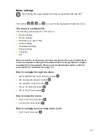
Page 20: ...t right FS full screen top button FS full screen full screen Mode Switch from distance to reading mode and reverse When switching to the distance viewing mode the stand illumination is switched OFF th...

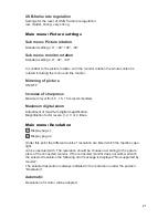
Page 21: ...recommended Maximum digital zoom Adjustment of maximum digital magnification Magnification factor levels 0 2 3 or 4 times Main menu Resolution Display page 1 Display page 2 Under this point the differ...

Page 22: ...olour foreground colour The following options enable the compilation of user defined artificial colours select the mode user defined artificial colours shift to main menu select the position colour se...

Page 23: ...in 15 min 30 min 1 h 2 h OFF Standby mode is switched OFF The standby mode can be set to different values between 2 minutes to 2 hours The camera will switch to the standby mode if the document has no...

Page 24: ...alternative settings with cursor enter the menu by pushing the button change the assigned function by pressing the button leave menu by pushing the button The alternative settings can be recalled whe...

Page 25: ...n to a 20x magnification when pushing the button Main menu Languages Deutsch French Dutch English Note Connect remote control to several devices The remote control can operate up to twelve topolino sy...

Page 26: ...To achieve the optimal image display the following minimum requirements are recommended Processor Intel P4 3 Ghz Memory 512 MB RAM Drive CD or DVD drive Graphic card with 32 MB and Overlay Operating s...

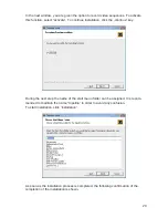
Page 27: ...ur CD drive to start setup exe Note If a warning window of the manufacturer of this software appears click yes To choose the language settings for the installation and the user interface of the softwa...

Page 28: ...ick the next continue key Note In the bottom left hand part of the window display the necessary fixed disk storage and the available memory is indicated Please make sure that adequate disk space is av...

Page 29: ...click the continue key During the next step the name of the start menu folder can be assigned It is recom mended to maintain the name topolino in order to avoid any confusion To start installation cl...

Page 30: ...to go to the next step Finally finish the installation wizard by clicking finish Installation of your topolino software is now completed and the program can be started and accessed through your window...

Page 31: ...e currently displayed on the monitor can be printed Exit With this menu item the program can be terminated Camera Zoom Increase or decrease the magnification levels Focus Turn the Autofocus feature ON...

Page 32: ...e magnified material You can control and adjust the depth or width of the window Line Marking allows you to create a vertical or horizontal red line or ruler Selecting Ruler Mask Switch Mode once will...

Page 33: ...mage transmission Auto AVI Decompressor Colour Space Converter None It is recommended to set the transferring images to automatic AF Help Shortcut Keys With this menu bar you can view the list of all...

Page 34: ...witch Activate and then switch between the options vertical ruler horizontal ruler vertical line coverage and horizontal line coverage Line marker Shadowing reverse Deactivate the ruler and mask Line...

Page 35: ...s will result in the invalidation of the warranty 4 Interventions from persons other than Reinecker Vision GmbH authorised special ists may lead to invalidity of warranty 5 Not included in this warran...

Page 36: ......

Page 37: ......

Page 38: ...Notes...

Page 39: ...no capo light V2 0 Serial Number Manufacturer Reinecker Vision GmbH Final examination Power supply 100 VAC 240 VAC 50 60 Hz over plug in power supply 12 VDC 5 0 A Type WTI205000 Power consumption appr...

Page 40: ...thorized distributor Reinecker Vision GmbH Zentrale Deutschland und Export Vertrieb Kundenberatung Sandwiesenstra e 19 64665 Alsbach H hnlein Kundendienst Erlenweg 3 64665 Alsbach H hnlein Tel 0 18 05...
Reviews: