background image

11

After Sales Support

UK/N.IRELAND HELPLINE N

O

:

REP.IRELAND HELPLINE N

O

:

WEBSITE:
EMAIL: 

01270 508538

1800 995 036

www.quesh.co.uk

enquiries@quesh.co.uk

Installation

Completing The Mount

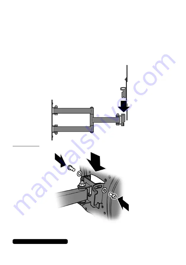
Remove the screws and washers from the rear plate bracket.
Lift the TV/monitor into place making sure the ‘V’ cut out on the 
base of the rear plate bracket is resting on the side stanchions of 

the wall arm.

Please Note:


This process may require two people.

Refasten the screws and washer to secure the rear bracket to the 

wall arm.

Summary of Contents for 20710

Page 1: ...SER GUIDE Full Motion TV Wall Bracket MODEL NUMBER 20710 After Sales Support UK N IRELAND HELPLINE NO REP IRELAND HELPLINE NO WEBSITE EMAIL 01270 508538 1800 995 036 www quesh co uk enquiries quesh co uk ...

Page 2: ... Fitting The Plate Fitting The TV Mount Completing The Mount Adjustments Adjusting The Viewing Angle Alternative Installation Stud Wall Specifications Copyright 2019 Thunderbolt Photography Richard Ross All rights reserved All Photos and Illustrations may not be reproduced or used in any manner whatsoever without the express written permission of the copyright holder ...

Page 3: ...d helpline We hope you enjoy using this product for many years to come If you require technical support or in the unlikely event that your purchase is faulty please telephone our helpline for immediate assistance Faulty product claims made within the 3 year warranty period will be repaired or replaced free of charge provided that you have a satisfactory proof of purchase keep your receipt safe Thi...

Page 4: ...ick mounting only 10mm Twist drill bit Stud mounting only Hammer action drill Hammer Large flat head or pozidrive screwdriver 10mm Spanner or socket wrench Keep the work environment trip and hazard free before beginning and during installation Always refer to the manufacturers safety instructions and guides before using power tools After Sales Support UK N IRELAND HELPLINE NO REP IRELAND HELPLINE ...

Page 5: ...55mm Coach Screw 4 x 10mmØ x 50mm Wall Plug 4 x 5mmØ Washer 8 x 6mmØ Washer 4 x 8mmØ Washer 4 x M4 x 14mm Screw 4 x M5 x 14mm Screw 4 x M6 x 14mm Screw 4 x M8 x 14mm Screw 4 x M6 x 12mm Bolt 4 x M6 Nut 1 x Cable Tie 1 x Mini Bubble Level Features Mounts up to VESA 400mm x 400mm 180 Triple Articulated Arm Arm Reach 65mm to 420mm 5 to 15 Screen Tilt 30Kg Max load Cable tie Multi Position Arm Mounts ...

Page 6: ...esh co uk enquiries quesh co uk Pouch Parts List A B C WALL FITTINGS M6 x 55mm Coach Screw 10mmØ x 50mm Wall Plug 6mmØ Washer G F D E H I J VESA MOUNT FITTINGS M4 x 14mm Screw M5 x 14mm Screw M6 x 14mm Screw M8 x 14mm Screw 5mmØ x 14mm Washer 6mmØ x 14mm Washer 8mmØ x 14mm Washer K L ARM FITTINGS M6 x 12mm Bolt M6 Nut ...

Page 7: ... pencil being careful not to move the plate Alternatively you can trace the outline and holes of the plate on to a blank piece of A4 paper Level the drawn guide with the bubble level and use that to guide you where to drill the holes Placing The Bracket Test place the wall bracket around the room until you find the best suitable location for it then draw a rough centre line on your chosen location...

Page 8: ...k platform to minimise risk of injury whilst using power tools You will need to drill a smaller pilot hole before the larger 10mm hole This will minimise any possible damage and injury or accidents Fit the 4mm or 5mm masonry drill bit to the hammer drill Place the wall plug next to the drill bit with the tips level Wrap a little masking or electricians tape about 5mm above the height of the wall p...

Page 9: ...The Plate First place the wall plugs into the drilled holes and tap in gently with a hammer to seat them flush to the wall Next insert the M6 x 55mm coach screws pouch A through the 6mmØ washers pouch C ready for use Line the holes of the plate to the drilled holes on the wall and insert the screws Tighten with a 10mm spanner or socket wrench until securely tight B C A ...

Page 10: ...0 995 036 www quesh co uk enquiries quesh co uk Installation Once the plate has been securely fitted place the cover cap to hide the bolts and neaten up the fitting Safely secure power tools after you have finished drilling Brush and wipe down surfaces free of brick dust and hoover the work area clean ...

Page 11: ...ng The TV Mount Check the TV monitors mount placement holes Once checked place the arms in the correct orientation on the rear plate Secure the arm in place by inserting the M6 x12mm bolt pouch K through the arm s square hole making sure the arm notch lines up with the rear plate Use the M6 nut pouch L to lock the arm in place using 10mm spanner or socket wrench L K ...

Page 12: ...being careful not to damage or scratch the screen place the rear mount into position lining up with the VESA mounting holes Check your TV instructions to find out the correct size screws to use to secure the rear plate in place Use the correct sized screw from pouch I J K and the correct washer from pouch D E F J and tighten with a large flat head or pozidrive screwdriver G H I J D E F ...

Page 13: ...tallation Completing The Mount Remove the screws and washers from the rear plate bracket Lift the TV monitor into place making sure the V cut out on the base of the rear plate bracket is resting on the side stanchions of the wall arm Please Note This process may require two people Refasten the screws and washer to secure the rear bracket to the wall arm ...

Page 14: ...ustments Adjusting The Viewing Angle Loosen the screws at where the rear mount attaches to the wall arm Tilt the screen in to the preferred position and tight the screws again Choose between the limits of 5 through to 15 Move the three 180 joints to move the TV monitor close or further away from the wall as well as to adjust the screen facing direction ...

Page 15: ...ly have the studs placed 406mm 16 approximately apart but they can be spaced up 609mm 24 with an approximate thickness of 36mm 1 If you have a double stud you will be able to mount the bracket on this without a bracket mount board Mount in the same way as listed on page 5 to 7 but instead of using a masonry drill bit use a twist drill bit general purpose Stud Stud Plasterboard Bracket Placement Be...

Page 16: ...ould be 260mm Use a twist drill bit to drill the holes to mount the board to the studs loosely secure in to place as you will need to remove it after the next step Once the board is fitted place the bracket in to position and mark the holes the same as page 5 Remove the board from the wall and drill the placement holes for the bracket You will need to counter sink the rear holes to accommodate the...

Page 17: ...s that this product is in compliance with Directive 2014 53 EU The full text of the EU declaration of conformity is available at the following internet address www quesh co uk Specification 2 4Kg 70mm x 222mm 65mm to 420mm 30Kg 400mm x 400mm General Approx Weight Approx Mounting Plate Dimensions Approx Arm Reach Max Supported Weight Max VESA Size Full Motion TV Wall Bracket ...

Page 18: ...y packaged so as to ensure that no damage occurs in transit Also make sure that you have included a detailed explanation of the problem Extent of the Warranty This warranty is limited to defects in workmanship or parts All defective products or parts will be repaired or replaced This warranty does not extend to accessories Normal Wear and Tear This warranty does not cover normal wear and tear of t...

Page 19: ...her with your warranty card Fault Description Name Address Date of purchase Location of purchase We recommend that you attach a photocopy of your receipt showing the date of purchase to this warranty card and keep it for your reference In the event of a product fault please call the After Sales Support team Please ensure that you have the product details as shown on this card to hand so that the s...

Page 20: ......

Reviews: