2
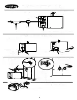
DRAIN VALVE OPTION
(According to Local
Plumbing Code.) 3/4 inch rigid copper piping must be
installed from the steam generator location to a drain.
Ensure that all water is able to drain from all sections
of the drain line at all times. Ask dealer for automatic
drain details.
ELECTRICAL - WATTS, WIRE AND FUSE SIZES
According to local electrical code. Use copper wire only.
Must be installed by qualified Electrician.
STEAM GENERATOR:
JR-3
JR-4
WATTS
6,000
9,000
Hz
60
60
Phase
1
1
208 VOLTS
Fuse/Breaker Size
40 Amp
60 Amp
Copper Wire - Supply
#8 AWG
#6 AWG
Copper Wire - Switch
#22 AWG
#22 AWG
240 VOLTS
Fuse/Breaker Size
40 Amp
50 Amp
Copper Wire - Supply
#8 AWG
#6 AWG
Copper Wire - Switch
#22 AWG
#22 AWG
Check to ensure that the supply voltage (either 208V or
240V) is compatible with the voltage listed on the
steam generator identification label (below water
supply). The fuses or circuit breaker must be of
adequate size to carry the necessary amperage to
operate the steam generator.
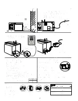
Select a convenient location in the steam room, within
20 feet of the steam generator, (5 feet up from the
finished floor,
away from the area above the steam
nozzles
) to install the Quick Touch Timer (found in the
appliance electrical box) and cord set packaged with
steam unit. Cut a 7/8 inch hole in the wall material and
pass the female end of the cord set through the wall for
final installation.
OR
, the Time and Temperature
Control with remote may be installed
(purchased
separately)
. ASK DEALER FOR DETAILS.
There is one copper “2 wire and ground power cable”,
class 1 wire, and one factory supplied “25 foot control
wire”, class 2 wire, to be run to the steam generator:
a -
Run a copper power supply cable, 2 wire and
ground of adequate gauge to carry the
necessary amperage from the fuse or circuit
breaker to the steam generator location.
b -
Run the factory supplied “25 ft cord set” from the
steam generator location to the Timer Control
location. Leave sufficient length at each end of
cord set for the final installation connections.
SEE
“CAUTION 8, 9 and 10
".
THE ELECTRICAL
”SUPPLY”
FOR THE STEAM
GENERATOR
CAN NOT
BE SWITCHED DIRECTLY
BY THE TIMER CONTROL SUPPLIED WITH THE
STEAM GENERATOR.
Use Copper Supply Wire Only
.
The copper power supply cable must run directly, from
the fuse or circuit breaker to the steam generator. The
factory supplied cord set must be run directly from the
steam generator to the Timer Control. The Timer
Control activates a contactor in the steam generator,
through the class 2 voltage circuitry.
STEAM PIPING TO BATH OR SHOWER
(½ inch rigid
copper pipe required) Install two ½ inch rigid copper pipes
(maximum 20 feet each) from the steam generator to where
they will enter the steam bath area, in a location where the
steam will not burn anyone. Insulate the steam pipes for
maximum efficiency. WARNING STEAM NOZZLE IS HOT
The end of the steam pipes in the steam room should each
have a ½ inch female pipe thread fitting that is attached to
something solid, (example: a “wingback 90 elbow” used to
rough in a shower head). For steam nozzle location
purposes during rough-in, install ½ inch iron pipe nipples
into the two female fittings (hand tight) so they will protrude
through the wall into the steam room. After the finished
walls are in place, the iron nipples are to be replaced by
brass nipples the appropriate length. See
“FINAL
INSTALLATION STEAM PIPING”
and
Fig, 3
.
1 - Steam Nozzle
2 - Escutcheon
3 - Finished Wall
4 - Sealer (silicone)
5 - ½” Brass Nipple
6 - ½” C x FIP. Adapter
7 - ½” Rigid Copper Pipe
8 - ½” CxC Wing Elbow
9 - 12" from steam pipe
to steam room floor.
Warning: Steam Nozzle is HOT
In a shower or steam room the centre of the brass nipples
and steam nozzles must be 12 inches above the finished
floor, and in a location away from the users pathways,
where the steam will not burn anyone, preferably on the
same wall as the shower head. See
“Figure 4"
.
If the steam nozzles are installed too low, the steam will
strike the floor (may cause damage to tile grout) and
condense into water before it can heat and steam the room.
Installing the steam nozzles correctly, in the lower part of
the room ensures a more even distribution of the heat and
steam.
It is not recommended
to place the steam
nozzles under a bench,
as there is a distinct
possibility that someone
sitting on the bench
could inadvertently put
their feet underneath it
and be burned. When
the steam nozzles are
under a bench it is
sometimes impossible
for the heat and steam
condensate to circulate
throughout the room.

