3
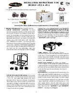
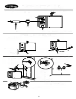
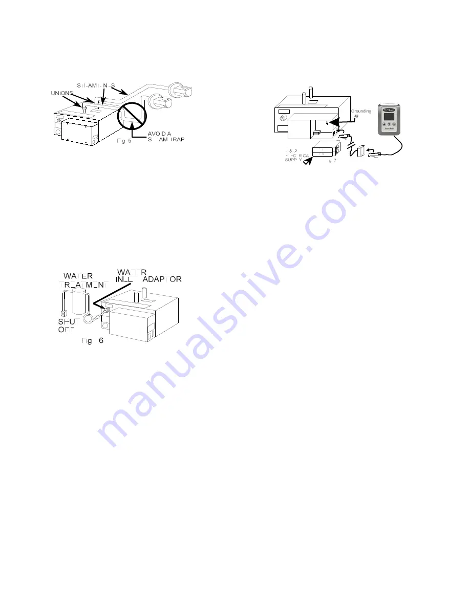
Care MUST be taken to AVOID A STEAM TRAP!
Water must be able to drain from all sections of the
steam pipes at all times. See
“CAUTIONS 1 AND 2"
and
Fig. 5
.
3. FINAL INSTALLATION
WATER SUPPLY
(According to Local Plumbing Code)
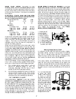
The water inlet connection on the steam generator
is a male garden thread. A swivel garden hose to
3/8 inch tubing adaptor is supplied for the installer’s
connection. The swivel adaptor will be a union.
Install a shut off on the water supply and reduce it to
use 3/8 inch O.D. soft copper tubing. Use 3/8 inch
O.D. soft copper tubing between the shut-off and
the swivel adaptor at the steam generator. Form a
“loop” in the 3/8 inch soft copper tubing to ensure
the boiler is being installed level. See
Fig. 6
.
DRAIN VALVE OPTION
(According to Local Plumbing
Code.) Install the shut off (purchased separately)
within 1 foot of the steam unit, between the 3/4 inch
copper female adapter and a 3/4 inch union
attached to the drain line. For the automatic drain
option, ask your Dealer for details.
ELECTRICAL
(According to Local Electrical Code.)
Check to ensure that the supply voltage (either
208V or 240V) is compatible with the voltage listed
on the steam generator identification label (below
the water supply). Pull the roughed-in copper
supply cable (2 wires and ground) into the steam
generator electrical connection box using the knock
outs and proceed with “a & b” as follows; move the
control cord set to the outside right of the electrical
connection box and proceed with “c & d” as follows:
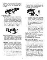
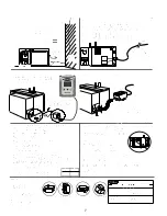
a -
Connect the copper power supply ground wire
to the Relax-A-Mist grounding lug inside the
appliance’s electrical connection box.
b -
Connect the two copper wires from the
power supply, one to each of the “L1 & L2
Terminals”. See
Fig. 7
.
The following instructions are for the
Quick Touch
Timer
. If you have purchased the Time and
Temperature Control with remote or an alternate
control, refer to their “Installation Instructions” now
and then return to “STEAM PIPING”.
c -
On the side panel of the steam generator
electrical box, remove the protective label
marked
“Remove To Insert Modular
Connector”
from the rear modular female
plug. Front plug is for Optional Automatic
Drain. Insert the male plug of the Timer cord
set, retaining tab to bottom, into the female
plug. See
Fig. 7
and electrical diagram
Page 7
.
d -
At the Timer Control location, remove the
protective label from the female connector on
the cord set. Insert the male plug from the
Quick Touch Timer wire, into the female
connector so the retaining tab locks in place
with an audible “click”. See
Fig. 7
and
electrical connection diagram
Page 7
.
C
DO NOT CUT FACTORY WIRING TO INSTALL
TIMER SWITCH.
C
DO NOT FORCE CONNECTIONS.
C
DO NOT ADHERE QUICK TOUCH TIMER TO WALL
UNTIL QUICK TOUCH TIMER PRETEST IS
SUCCESSFULLY COMPLETED.
C
SEE
“CAUTIONS 6, 7, 8, 9, 10, 11 and 12"
.
QUICK TOUCH TIMER PRETEST
i - With the water supply and the power supply turned
on, the Quick Touch Timer display will illuminate two
horizontal bars. This indicates the Timer is
connected and has power. If the Timer display does
not illuminate horizontal bars, check all electrical
connections and correct. If problem persists, call 1-
800-Y-U-STEAM (1-800-987-8326) Monday to
Friday, 8:00am to 4:30pm Pacific Standard Time or
e-mail technical support@relax-a-mist.com for
assistance.
ii - When the display illuminates the horizontal bars,
press the “on/off” button. The display will show 30
minutes. Listen to hear the generator filling with
water and the audible click of the contactor closing.
When the water valve finishes filling the unit , arrow
the time control down to zero. When zero is
reached, the horizontal bars will appear and the
steam unit will turn off. This successfully completes
the pretest. The Quick Touch Timer may now be

