background image


User Manual RelAir ICS ·03/2019 · VERSION 1.0 

RelAir ICS 

3 Telegram description 

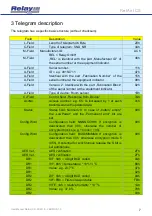
The telegram has a specific basic structure (without checksum):


Field 

Description 

Value 

L-Field 

Length of telegram 46 Byte 

2Eh 

C-Field 

Type of telegram: SND_NR 

44h 

M-Field 

Manufacturer-ID: 

REL = Relay GmbH 
„REL“  is  identical  with  the  part  „Manufacturer  ID“  of 
the serial number at the equipment indicator. 

ACh 

M-Field 

48h 

A-Field 

Serial number: 
ID = e.g. 08154711 
Identical  with  the  part  „Fabrication  Number“  of  the 
serial number at the equipment indicator. 

11h 

A-Field 

47h 

A-Field 

15h 

A-Field 

08h 

A-Field 

Version: 2; Identical with the part „Fabrication Block“ 
of the serial number at the equipment indicator. 

02h 

A-Field 

Type of device: Room sensor 

1Bh 

Ci-Field 

Control field: „Response from Device” 

7Ah 

AccNo 

Access  number:  e.g.  65.  Is  increased  by  1  at  each 
transmission with updated data. 

41h 

Status 

Status  field:  Normally  0.  In  case  of  „battery  empty“ 
the  „LowPower“  and  the  „Permanent  error“  bit  are 
set. 

00h 

Config.Word 

Configuration  field:  NNNNCCHHb  If  encryption  is 
deactivated  then  00h,  otherwise  the  number  of 
encrypted blocks (e.g. 1 block = 10h). 

00h 

Config.Word 

Configuration  field:  BAS0MMMMb  If  encryption  is 
deactivated  then  00h,  otherwise  encryption  mode  5 
(05h). If potential for synchronous release the S bit is 
set additionally. 

00h 

AES Ver. 

AES verification 

2Fh 

AES Ver. 

AES verification 

2Fh 

DR1 

DIF: 0Ah = 4 Digit BCD coded 

0Ah 

DR1 

VIF: 66h = temperature * 10^(-1) °C 

66h 

DR1 

Value: e.g. 23,7°C 

37h 

DR1 

02h 

DR2 

DIF: 0Ah = 4 Digit BCD coded 

0Ah 

DR2 

VIF: FBh = First extension table 

FBh 

DR2 

VIFE: 1Ah = relative humidity * 10

-1 

1Ah 

DR2 

Value: e.g. 37,8% 

78h 

DR2 

03h 


Summary of Contents for RelAir ICS

Page 1: ...Wireless M Bus and OMS Indoor Climate Sensor RelAir ICS Temperature and relative humidity User Manual...

Page 2: ...g 3 2 4 Mounting plate 4 2 5 Circuit board 5 2 5 1 Remove the Circuit board 5 2 5 2 Configuration 5 2 5 3 Insert batteries 6 2 5 4 PCB mounting 6 2 5 5 Front Cover 6 3 Telegram description 7 4 Label 8...

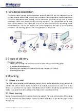
Page 3: ...pplication of the sensor 2 Scope of delivery Equipment supplied OMS radio humidity and temperature sensor with casing and mounting plate 2 AA size alkaline batteries Mounting set consisting of 2 dowel...

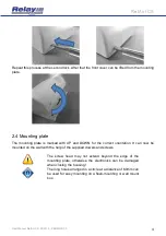
Page 4: ...is marked with UP and DOWN for the correct orientation It can now be mounted on the wall with the help of the supplied dowels and screws The screw head may not extend beyond the edge of the mounting...

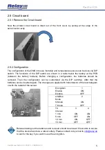
Page 5: ...lders Before changing a configuration the batteries should be removed Then the configuration can be customized via the DIP switches After that the batteries can be inserted again The changes are appli...

Page 6: ...4 PCB mounting Thereafter the circuit board with the batteries ahead is placed back into the front cover Attention on the orientation On the circuit board and on the label of the Front cover it is mar...

Page 7: ...ce Room sensor 1Bh Ci Field Control field Response from Device 7Ah AccNo Access number e g 65 Is increased by 1 at each transmission with updated data 41h Status Status field Normally 0 In case of bat...

Page 8: ...Fh Fill Fill byte 2Fh Fill Fill byte 2Fh Fill Fill byte 2Fh Fill Fill byte 2Fh Fill Fill byte 2Fh Fill Fill byte 2Fh Fill Fill byte 2Fh Fill Fill byte 2Fh Fill Fill byte 2Fh Fill Fill byte 2Fh Fill Fi...

Page 9: ...ransmit mode S1 or T1 unidirectional Frame Format A Encryption Mode 0 not encrypted or Mode 5 Transmit interval Configurable by DIP switches 1 min 5 min 10 min 15 min 5 3 Power Supply Battery 2 replac...

Page 10: ...User Manual RelAir ICS 03 2019 VERSION 1 0 10 RelAir ICS 6 CE Declaration...

Page 11: ...User Manual RelAir ICS 03 2019 VERSION 1 0 11 RelAir ICS Notes...

Page 12: ......

Reviews: