WebLog120 · Hardware User Manual Version 1.0 - 12/2022
5
WebLog120
Lower terminals (from left to right):
Type
Signal
Description
LAN 1
10/100 MBit RJ45 Ethernet socket for a network connection
LAN 2
10/100 MBit RJ45 Ethernet socket for a network connection
MICRO-SD
Holder for an optional micro SD card (push-push mechanism)
USB 1
USB host port #1
USB 2
USB host port #1
TERM
ON / OFF
Slide switch for switching the 120
Ω
terminating resistor of the RS485 on
and off
RS485
B- / A+ / GND
RS485 interface, 2-wire, B = - / A = + / GND = ground reference
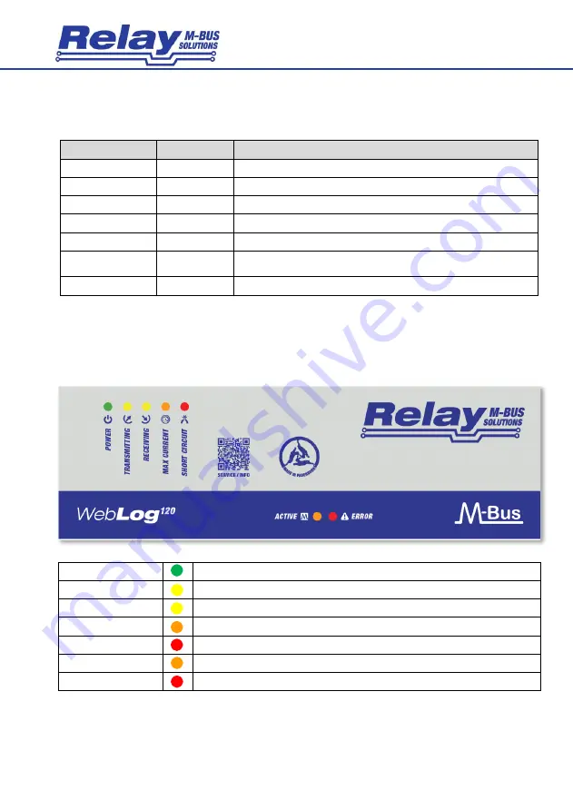
2.4 LED Indicators
A total of 7 LEDs in the front cover indicate the status of the M-Bus and the system. A lighted LED has the
following meaning:
POWER
The M-Bus output voltage is switched on
TRANSMITTING
The master sends data
RECEIVING
At least one meter responds with data
MAX CURRENT
The maximum number of meters has been exceeded (warning current)
SHORT CIRCUIT
M-Bus overcurrent / short circuit (2 Hz flashing)
M-BUS ACTIVE
The WebLog120 occupies the M-Bus exclusively ( Repeater off)
ERROR
New unread error message(s) in event log


