WebLog120 · Hardware User Manual Version 1.0 - 12/2022
7
WebLog120
3.1 Interfaces
The transparent RS232C and Repeater interfaces are always connected directly to the internal M-Bus level
converter when the WebLog120 is not reading the M-Bus meters itself.
The LED labeled ACTIVE shows the activity status of the internal interface switch. While this LED is lighted,
the CPU is active on the M-Bus, i.e. the other interfaces are deactivated during this time and cannot access
the M-Bus. As soon as the LED goes out, an external controller (PC) can read the M-Bus via RS232C or
repeater.
3.2 RS232C Interface
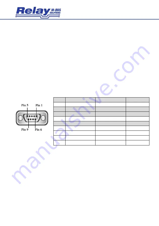
The WebLog120 offers an RS232C interface that is transparent to the M-Bus and is connected via a 3-pin
screw terminal. The assignment is as follows: TX = PC receives from M Bus, RX = PC transmits to M Bus,
GND = signal ground. If you want to connect a D-SUB cable, please use the additional, optional cable KA006
with 3 open wires. To connect to a PC (1:1 connection), connect the 3 wires as follows:
D-SUB
Signal
Function WebLog120
Colour (terminal)
Pin 1
DCD (data carrier detect)
unused
Pin 2
RXD (PC receives data)
M-Bus sends data to PC
green (TX)
Pin 3
TXD (PC sends data)
PC sends data to M-Bus
yellow (RX)
Pin 4
DTR (data terminal ready)
unused
Pin 5
GND (signal ground)
GND
black (GND)
Pin 6
DSR (date set ready)
unused
Pin 7
RTS (request to send)
unused
Pin 8
CTS (clear to send)
unused
Pin 9
RI (ring indicator)
unused
3.3 RS485 Interface (optional)
The RS485 interface will be available in a future version of the WebLog120 as an interface to the internal CPU,
but not as a transparent interface to the M-Bus.
A 2-wire RS485 interface is connected to the terminals marked RS485 (A = + and B = -). With the help of the
slide switch labeled "TERM", you can activate a 120
Ω
terminating resistor between terminals A+ and B- as
required.


