Forest Grove, Oregon 97116 USA
(503) 357-5607 or (800) 382-3765
General
Specifications
FBT-5
Fieldbus Wiring
Validator
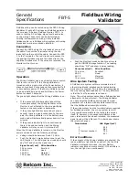
Fieldbus wiring can be tested using the FBT-5 Wiring
Validator. It puts a DC voltage and fieldbus signals on
the wire pair. A Relcom Fieldbus Monitor, FBT-3, is
used to test the DC voltage, signal levels and noise
on the wiring. These tests can be performed on
existing instrumentation wiring, newly installed
fieldbus cable, or a fieldbus wiring system with wiring
blocks and terminators already installed.
Connection
Connect the FBT-5 using the clip leads at one end of
the cable. Connect the Terminator using the clip
leads to the other end of the cable. Connect the FBT-
3 to the Terminator. The red clips should connect to
the positive Fieldbus wire and the black clips to the
negative Fieldbus wire. If the wires are reversed, the
Monitor will not turn on.
Operation
The Wiring Validator has a push-button Power switch
that turns it on or off. If the Wiring Validator is
turned on with a single click of the Power button, it
stays on for about 5 minutes and then turns itself off
to save battery power. If the Wiring Validator needs
to be on indefinitely, push and hold down the Power
button for about 3 seconds.
The green light shows that the Wiring Validator is on.
•
If the green light blinks rapidly (about three
times per second) the Wiring Validator or the
Monitor is not attached to the wire pair being
tested or the connection is backwards.
•
If the green light blinks slowly (about once a
second) there is a good connection to the wire
pair, the Wiring Validator is in the battery save
mode and will automatically power down in five
minutes.
•
If the green indicator light is on continuously
there is a good connection and the Wiring
Validator will stay on until it is turned off.
When the Wiring Validator is turned on, the Monitor
powers up and shows the following readings.
•
Voltage should be between 9 and 10 Volts
•
Push the Monitor's mode button once to get the
LAS function. The LAS signal level reading should
say "OK" and show the signal level.
Signal Level (mV)
Wire Condition
350 or more
Excellent
200-350
Good
150-200
Marginal
150 or less
Not Good
•
Push the Monitor's mode button three time to
get the NOISE AVerage function. The reading
should say "OK" and show a noise reading.
Noise Level (mV)
Wire Condition
25 or less
Excellent
25-50
Good
50-75
Marginal
75 or more
Not Good
Wire System Testing
A fieldbus wire system with two terminators and
other wiring blocks installed can be tested before
devices are connected. This is done the same way as
the wire testing described above. The only difference
is that the Test Terminator is not used.
Note: The wiring system cannot have fieldbus devices
attached to it during the test. The Wiring Validator
can not power the fieldbus devices and its signal
generator will interfere with any data transmission
that the fieldbus devices might initiate.
If the wiring system has the two terminators required
for fieldbus operation, the wiring system test will
have results comparable to the testing the wire by
itself. If, however, not enough terminators or too
many terminators have been installed, the measured
signal levels will be different. The chart below shows
the relative changes:
Terminators
LAS Signal (mV)
0
999
1
961
2 (correct number)
760
3
637
Error Conditions
If the outputs of the Wiring Validator are shorted, the
red Low Battery light blinks on and off. (As the Wire
Validator is attached to wires, the Low Battery
indicator may blink on momentarily). If the battery is
low, the red light is on continuously.


