7
Section 7 - Wiring
7.1 Wiring Instructions
- Wiring should be in accordance with the national electrical code and any local codes or
regulations. Have a licensed and competent electrician ensure that the voltage supplied
matches the compressor voltage.
- Inadequate wiring size can cause insufficient voltage at the compressor during start-up.
Overheating and damage can result to the motor and controls.
- Failure to use the pressure switch may result in overpressure of the compressor or other
components in the system. Overpressure of the compressor can result in blown head
gaskets or other damage.
- Grounding Instructions: This product must be connected to a grounded, metallic,
permanent wiring system, or an equipment grounding terminal or lead on the product.
The supply wire must be of adequate size and no other equipment should be
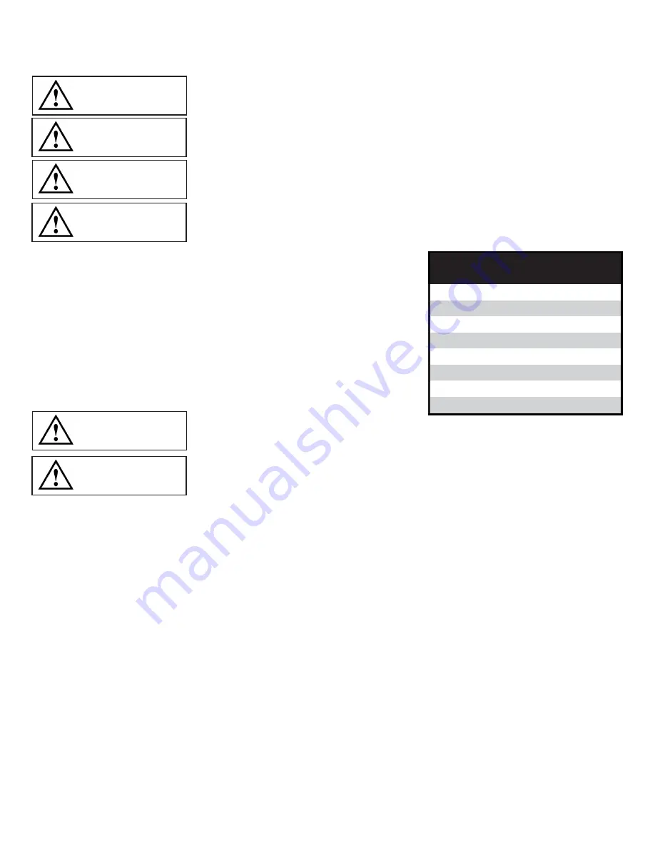
connected to the same line. The adjacent table lists the recommended wire
size for each model based on a 100’ run and lowest operating voltage. Consult
factory for longer runs. The motors supplied are multiple voltage motors. A
label on the pressure switch cover indicates the voltage the motor is pre-wired
for. If the supply voltage, on site, is different from the voltage indicated on this
label, change the internal motor voltage connections to match the supply
voltage. To change internal voltage connections, remove the cover plate
located on the rear or side of the motor and reconnect the wire leads as shown
on the motor’s wiring diagram.
- Single-phase motors include internal thermal overload protection, which has an
automatic reset device.
- Disconnect electrical power before servicing to disable reset devices. Thermal protection
can automatically start the motor when the protector resets.
The motor is pre-wired to the pressure switch provided, which controls starting (cut in pressure) and stopping (cut out pressure)
of the motor. The pressure switch is factory set. Riser mount models have the switch set at 20 psig cut in and 26 psig cut out.
Tank mount models have the switch set at 80 psig cut-in and 100 psig cut-out.
A motor starter can be used, for all single phase models.
Consult the National Electric Code and local codes for motor
starter requirements. Refer to the proper wiring instruction drawing for recommended wiring to a starter.
Minimum Recommended Wire Size
Model #
1 Phase
RRM23016-2026
12
RRM40033-2026
12
RRM70050-2026
12
RTM25033-80100
12
RTM36575-80100
10
RTM550100-80100
6
RTM915150-80100
6
RTM1100200-80100
10
WARNING
CAUTION
NOTICE
NOTICE
NOTICE
WARNING


