28
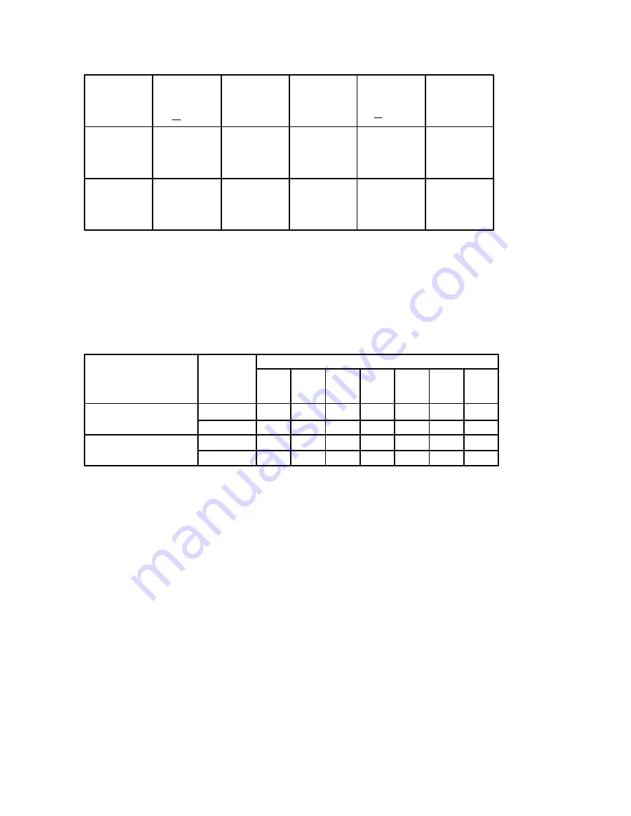
Table 26. Speed Regulation Characteristics.
1
Type of
Regulation
Line
Voltage
Load
Change
Regulated
Speed
Temperature
Field
Heating
+10%
95%
Range
+10
_
C
Cold
1
All percentages expressed relative to maximum speed.
2
Applies to wound field DC motors only.
3
Dependent upon specific motor characteristics and IR drop compensation adjustment.
4
Applicable to nonreversing models only.
Armature
Feedback
(Voltage)
Tachometer
Feedback
0.1%
0.1%
1%
20:1
30:1
1.0%
1.5%
512%
0.5%
25%
3
(Speed)
4
Normal
2
Table 27. Dynamic Braking Capabilities (with Switch Reversing
Models DC271, 78, 91 and 98 only).
Motor Horsepower
Description
Input
Voltage
1/4
1/3
1/2
3/4
11/2
2
1
Braking Torque
(% Full Load Torque)
115
230
115
230
129
-
12
-
103
-
11
-
66
200
8
8
44
190
6
6
34
130
2
1
-
88
-
1
-
62
-
1
Allowable Stops
Per Minute
Summary of Contents for DC2 VS series
Page 1: ......
Page 2: ......
Page 3: ......
Page 4: ......
Page 5: ......
Page 31: ...3 16 419 519 TB2 Motor Mounted D C Tachometer Figure 3 8 D C Tachometer Connection...
Page 48: ...5 6 Figure 5 1 Wiring Diagram of Basic Speed Controller 0 57210 30...
Page 49: ...5 7...
Page 51: ...5 9 J4...


