313
Wire the Run/Jog Circuit
For drives without operator devices on the controller:
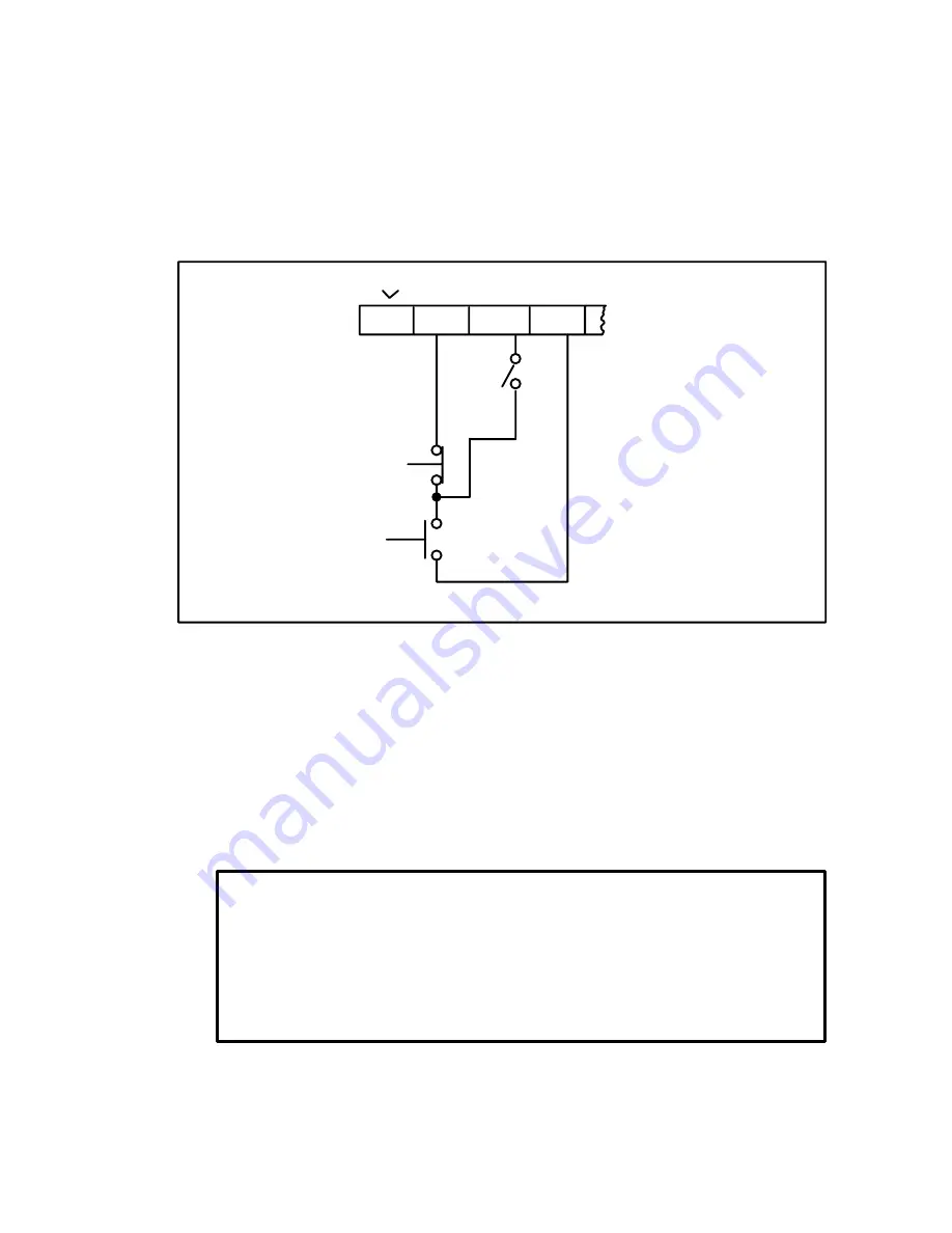
1. Run the Run/Jog wiring in conduit separate from the AC and DC
power wiring.
2. Use the appropriate tightening torque as listed in Table 32 for wire
connections to input and output terminals.
3. Wire the Run/Jog switch as indicated in Figure 36A.
32
132
35
38
4986917A
START
STOP
4986920
1> Jumper 32 to 132 or connect a motor thermostat.
1
JOG
Figure 36A. Basic Run/Jog Circuit Connections.
Wire the Reference Signal Potentiometer
For drives without operator devices on the controller:
1. Run all reference wiring in the same conduit as the Start/Stop
control wiring separate from the AC and DC power wiring.
2. Use the appropriate tightening torque as listed in Table 32 for wire
connections to input and output terminals.
3. Use #16 AWG cable that is twisted triple conductor with at least two
twists per inch.
DANGER
BECAUSE THE REFERENCE POTENTIOMETER IS CONNECTED THROUGH
THE REGULATOR TO THE ARMATURE POWER CIRCUIT, ITS TERMINALS
ARE AT LINE POTENTIAL. USE A POTENTIOMETER THAT HAS A PLASTIC
SHAFT TO INSULATE THE OPERATOR KNOB FROM THIS POWER CIRCUIT
AND THAT IS CAPABLE OF WITHSTANDING HIPOT TESTS AT 2000 VOLTS
DC FOR ONE MINUTE. FAILURE TO OBSERVE THIS PRECAUTION COULD
RESULT IN SEVERE BODILY INJURY OR LOSS OF LIFE.
4. Connect a 5K ohm, 0.25 watt pot having an insulated operator shaft
and knob, such as Reliance Model 14C230 or equivallent, as shown
in Figure 37.
Summary of Contents for DC2 VS series
Page 1: ......
Page 2: ......
Page 3: ......
Page 4: ......
Page 5: ......
Page 31: ...3 16 419 519 TB2 Motor Mounted D C Tachometer Figure 3 8 D C Tachometer Connection...
Page 48: ...5 6 Figure 5 1 Wiring Diagram of Basic Speed Controller 0 57210 30...
Page 49: ...5 7...
Page 51: ...5 9 J4...


