19
be applied to the controller, but the load is
not
conĆ
nected. It is important to follow these steps closely. ObĆ
serve all cautions and warnings.
DANGER
WITH AĆC POWER APPLIED AND WITH THE
POWER ON/OFF SWITCH IN THE ON POSIĆ
TION. HAZARDOUSVOLTAGE EXISTSIN THE
CONTROLLER. EXERCISE EXTREME CAUTION
WHEN PERFORMING THESE TESTS. PERĆ
SONAL INJURY CAN RESULT.
DANGER
IF CIRCUIT BREAKER HASTRIPPED OR FUSES
HAVE CLEARED THE FIELD SUPPLY, ITS WIRĆ
ING MUST BE INSPECTED FOR DAMAGE.
REAPPLYING POWER TO THE DRIVE, THE
FIELD VOLTAGE MUST BE REĆCHECKED FOR
PROPER VOLTAGE AT MOTOR TERMINALSF1,
F2. IF THISVOLTAGE ISBELOW 90% OF THE
FIELD VOLTAGE SPECIFIED ON THE MOTOR
NAMEPLATE, THE DRIVE MUST NOT BE
STARTED UNTIL PROPER VOLTAGE IS OBĆ
TAINED. FAILURE TO FOLLOW THISPROCEĆ
DURE COULD RESULT IN OVERSPEEDING THE
MOTOR AND/OR THE MACHINERY COUPLED
TO THE MOTOR SHAFT AND POSSIBLE FATAL
INJURY.
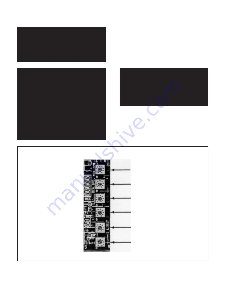
4.3.1 Regulator Module Pots
- TheRegulator Module
has six adjustable potentiometers mounted on it. (Refer
to Figure4.4.) They control thefollowing functions:
Maximum speed (full CCW: 50 Ć70% speed)
Minimum speed (full CCW: Drive Min. Speed 5%)
Acceleration rate (full CCW)
Deceleration rate (full CCW)
Current limit (factoryĆset at 150%)
IR comp (full CCW)
The potentiometers are factory preset for the safest or
most conservative operation.
DANGER
USE ONLY ON HAND TO HOLD THE SCREWĆ
DRIVER. KEEP YOUR OTHER HAND BEHIND
YOU. DO NOT USE YOUR OTHER HAND TO
BRACE YOURSELF AGAINST THE CONTROLĆ
LER, PANEL OR ENCLOSURE. PERSONAL INĆ
JURY COULD RESULT IF YOU ACCIDENTALLY
TOUCH A COMPONENT AT LINE VOLTAGE.
4.3.2 Maximum Speed (Voltage)
- TheMaximum
Speed Potentiometer on the Regulator Module has
been factory preset for 70% of a typical motor base
speed of about 1750 rpm. By means of adjustment, the
maximum speed may be raised to suit the application.
The result is the highest speed that can be set by the
MAX SPEED
MIN SPEED
ACC RATE
DECL RATE
CURRENT LIMIT
IR COMP
Figure 4.4 - Regulator Module Pots
Summary of Contents for MinPak Plus
Page 1: ......
Page 3: ......
Page 9: ......
Page 13: ......
Page 17: ......
Page 28: ......
Page 29: ......
Page 30: ......
Page 31: ......
Page 32: ...Figure 5 9 230 VAC Auxiliary Panel Assembly Schematics...
Page 33: ...Figure 5 10 460 VAC Auxilliary Panel Assembly Schematics...
Page 34: ......
Page 35: ......
Page 36: ......
Page 37: ......
Page 38: ......
Page 39: ...Figure 5 13B Technical Data 230 VAC Three Phase MinPak Plus...
Page 40: ......
Page 41: ...Figure 5 14B Technical Data 460 VAC Three Phase MinPak Plus...
Page 42: ......
Page 43: ......
Page 44: ......
Page 45: ......
Page 51: ......


