47
SECTION 7
THREE PHASE MINPAK PLUS MODIFICATION KIT
INSTRUCTION MANUALS
7.0 General
- A number of optional features in the
form of Modification Kits are offered with the three
phase, MinPak Plus controller. Each of these Kits exĆ
tends the control of the unit and tailors its operation to
specific application needs.
This Section describes the procedures that must be folĆ
lowed to install the Kits. Refer to Table 7.A for an informaĆ
tional listing.
DANGER
INSTALLATION OF MODIFICATION KITS IS TO
BE DONE ONLY AFTER AĆC LINE VOLTAGE IS
DISCONNECTED AND LOCKED OUT AT THE
MAIN DISCONNECT SWITCH. DO NOT INSTALL
KITS WHEN POWER IS APPLIED TO THE
MINPAK PLUS CONTROLLER. SERIOUS PERĆ
SONAL INJURY AND EQUIPMENT DAMAGE
COULD RESULT.
CAUTION:
Installation of the Modification Kits
should be performed only by qualified electrical
maintenance personnel familiar with the design
and operation of this equipment. Damage could reĆ
sult thru unfamiliarity.
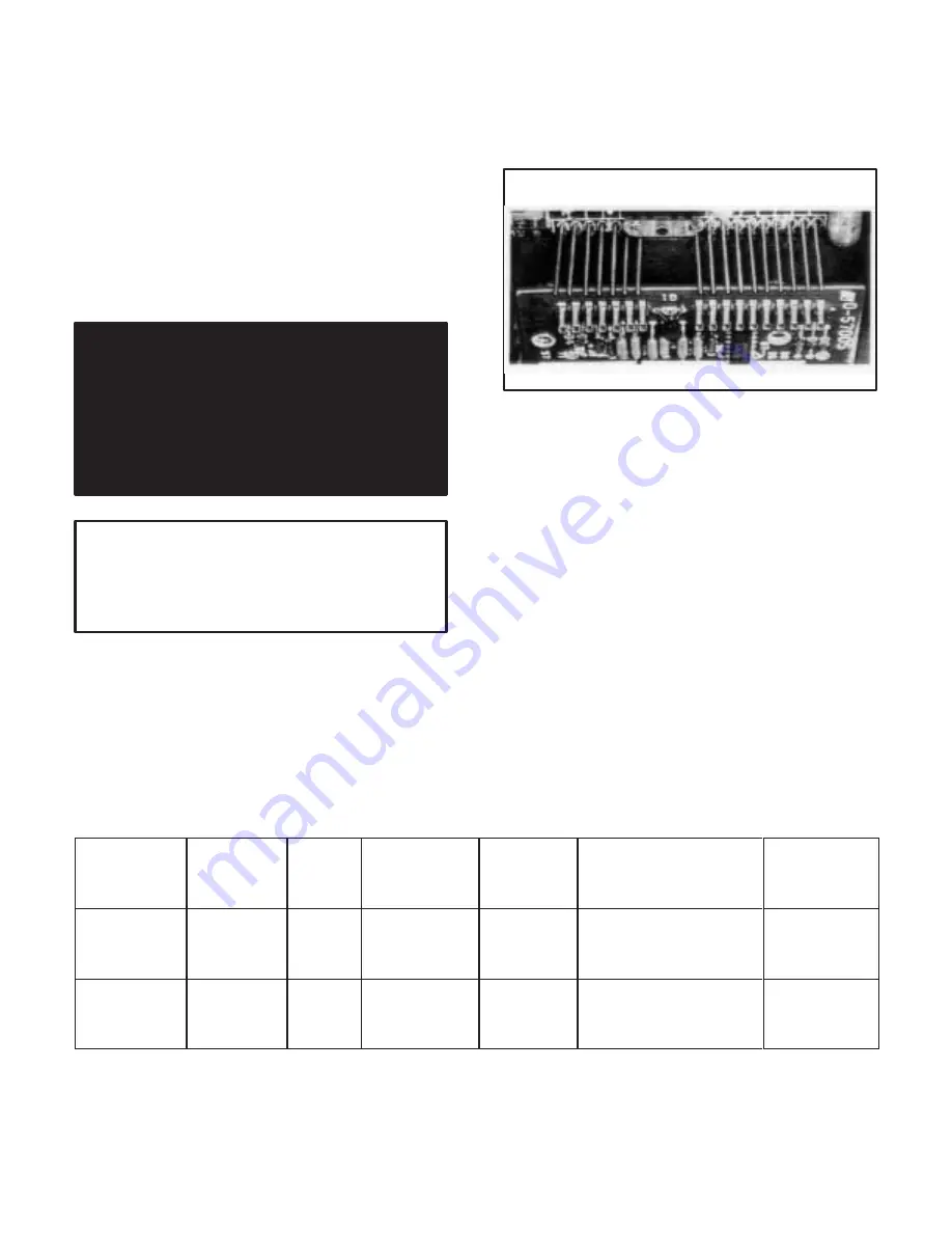
Many of the Modification Kits are designed to make
electrical connection with the Regulator Module by
means of pinĆtype connectors. These slide up through
matching holes in the Modules that form part of the Kit.
(Refer to Figure 7.1.)
Figure 7.1 - Pin Alignment
A common installation problem is caused by bent,
broken or incorrectly placed pins.
Since improper opĆ
eration results, care must be taken.
Exact alignment is
critical.
Visually check that only
one
pin extends to the
top of
each
slot once the connection is made.
Many of the Modification Kits require the removal of one
or more jumpers from the Regulator Module. In such
cases, carefully clip the leads on both sides of each
jumper and discard it. Use a sharp pair of dykes (diagoĆ
nal cutters) to assure a quick, clean cut. Do not twist the
tool, since damage may result.
In cases where the Kit is secured by a mounting screw,
be sure to tighten it firmly but
do not overtighten.
ExĆ
cessive force can strip the threads.
Table 7.A - Modification Kit Quick Reference List
Kit
Instruction
Manual
Number
Model
No.
Controller
Modification
?
➀
Additional
Options
Required
?
Options Required
Additional
User-
Supplied
Parts?
Local
Operator
Station
Faceplate
DĆ3977
14C201
thru
14C208
No
No
None
No
Dynamic
Braking
DĆ3957
14C420
thru
14C434
Yes
No
Auxiliary Panel
w/DB Pole on
Contractor
Standard
Wire
➀
Modification here means that some work such as jumper placement, resistor clipping, or wiring reconnection must be performed.
Summary of Contents for MinPak Plus
Page 1: ......
Page 3: ......
Page 9: ......
Page 13: ......
Page 17: ......
Page 28: ......
Page 29: ......
Page 30: ......
Page 31: ......
Page 32: ...Figure 5 9 230 VAC Auxiliary Panel Assembly Schematics...
Page 33: ...Figure 5 10 460 VAC Auxilliary Panel Assembly Schematics...
Page 34: ......
Page 35: ......
Page 36: ......
Page 37: ......
Page 38: ......
Page 39: ...Figure 5 13B Technical Data 230 VAC Three Phase MinPak Plus...
Page 40: ......
Page 41: ...Figure 5 14B Technical Data 460 VAC Three Phase MinPak Plus...
Page 42: ......
Page 43: ......
Page 44: ......
Page 45: ......
Page 51: ......


