- E
nglIsh
-
Operator’s manual
29
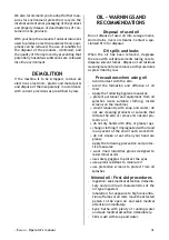
Tower does not tilt
Faulty tower tilt cylinder.
> Renew tower tilt cylinder.
No air supply to cylinder.
> Renew cock.
air escapes from cock.
> Renew cock or tower tilt cylinder.
arm and vertical slide locking cock leaks air
Valve seal damaged.
> Renew cock knob.
air leaks from air clamping cylinders
Faulty piston or seals.
> Change pistons and seals.
The tower tilts violently or slowly (fig. 24)
incorrect release valve setting.
> Adjust.
> Hares: increase speed.
> Tortoise: decrease speed.
Tyre pressure gauge needle fails to return
to 0
Pressure gauge faulty or damaged.
> Renew pressure gauge.
WarNiNG
The “Spare parts” handbook does not autho-
rise the user to carry out work on the ma-
chine with the exception of those operations
explicitly described in the user’s manual, but
enables the user to provide the technical
assistance service with precise information,
in order to reduce delay.
maiNTENaNCE
WarNiNG
The manufacturer declines all liability for
claims deriving from the use of non-original
spares or accessories.
WarNiNG
it is expressly forbidden to attempt to alter
operating pressure of the relief valves or the
pressure regulator.
The manufacturer declines all liability for
damage resulting from tampering with these
components.
WarNiNG
Before making any adjustments or carrying
out maintenance, disconnect the electrical
supply from the machine and make sure that
all moving parts are suitable immobilised.
WarNiNG
Do not remove or modify any parts of this
machine except in the case of service in-
terventions.
DaNGEr
When the machine is disconnected from the
air system, the devices bearing the above
plate may remain pressurized.
The FRL unit (filter, regulator and lubricator) is
installed to filter the air, regulate its pressure
and lubricate it.
The FRL unit withstands a maximum input pres
-
sure of 18 bar and has a regulation range from
0.5 to 10 bar. The setting can be modified by
pulling the knob to the OUT position and turning
it; after adjusting, return the knob to the locked
position by pushing it down (fig.32a).
The lubricating flow-rate is adjusted by tur
-
ning the screw on the element “L”, (fig.32b);
normally the unit is preset at a pressure of 10
Bar, with lubricant having viscosity SAE20, so
that one drop of lubricant is dispensed every
4 times the bead-breaker is operated (check
through the transparent cup).
Summary of Contents for PROMAXX 8150
Page 17: ...17...
Page 18: ...18...
Page 33: ...33...
Page 34: ...34...
Page 50: ...50...
Page 65: ...65...
Page 66: ...66...
Page 81: ...81...
Page 82: ...82...
Page 83: ...83 2 1 C A...
Page 84: ...84 4 3...
Page 85: ...85 5 6a 6 A B C mm A B E 8150 FI 8150 min 1570 750 870 max 1950 950...
Page 86: ...86 A N F G H M C O E B Q L S R T U P V 7...
Page 87: ...87 A B C D A A B C 10 8 9...
Page 88: ...88 13 11 12 A B C L H...
Page 89: ...89 16 14 15 G...
Page 90: ...90 19 17 18 M C 20...
Page 91: ...91 21 22a 22b N I...
Page 92: ...92 25 23 24 F D...
Page 93: ...93 28 26 27...
Page 94: ...94 29 30 a b...
Page 95: ...95 31...
Page 96: ...96 32...
Page 97: ...97 33 446694_2 3 ph...
Page 98: ...98 33 430710C2 1 ph...
Page 99: ...99 35 446726_2...
Page 100: ...100 35 446724_1 AIR MOTOR...
Page 101: ...101 35 453413 FI...
Page 102: ...102 35 453414 FI AIR MOTOR...
Page 103: ...103...
Page 107: ......

