37
Caution!
See remarks of 3.1.6 !
Replacing of the load chain, the chain guide and the hold down
If the load chain has to be replaced, the chain guide and the hold down have to be replaced too.
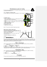
figure 1: Replacing load chain, chain guide and hold down
F o r s i n g l e f a l l v e r s i o n
Dismantling the worn out chain
23. Remove the chain collector (see remarks of 3.1.5)
24. Remove the load hook (four screws M12x60 DIN 912
– see remarks 3.1.7)
25. Remove the end stop (two screws M12x60 DIN 912)
26. Fit the connecting piece to the worn chain and connect a short piece of chain
27. Remove the load chain by pressing the button.
28. Remove the load chain by pressing the button until the short piece of chain has completely run into
the hoist.
29. Remove the worn chain.
Replacing the chain guide and holding down
30. Remove the cover of the contactor control (four screws M6x75 DIN 912)
31. Dismantle the shaft of the limit switches as follows:
Remove the two tension pins 5x30
Remove the snap ring and the torsion spring
Remove the shaft of the limit switches
32. Remove the two screws M16x120 DIN 912 of the chain guide in the control compartment of the
hoist.
33. Remove the chain guide. (underside of casing)
34. Remove the hold down (press it out with a screw driver)
35. Insert the new hold down and the new chain guide
The pick up of the two screws M16x120 DIN 912 should not be more than 60 Nm
– insert the screws with new gasket rings
36. Insert the shaft for the limit switches (see remarks 3.2.2)
37. Assemble the cover of the contactor control compartment.
Hold down
Sprocket wheel
Chain
guide
(two pieces)
Chain
suspension
Screw
for
chain
g
uide
Shaf
t f
or
lim
it
sw
it
ches
Screw
for
chain
g
uide
Bolt
f
or
chain
susp
en
si
on
Axl
e
susp
en
si
on
Bolt
f
or
chain
susp
en
si
on
Shor
t
piece
of
chain
connect
ing
piece


