6.5.8
Specific air and flue gas applications
Important
If the boiler is used in a flue gas overpressure cascade, this must
be stated on the sticker supplied: This central heating unit is set
for... This sticker must be affixed next to the data plate of the
boiler.
Contact us for more information.
6.6
Electrical connections
6.6.1
Recommendations
Warning
Electrical connections must always be made with the power
supply disconnected and only by qualified installers.
The boiler is completely pre-wired. Never change the internal
connections of the control panel.
Always connect the boiler to a well-earthed installation.
Establish the electrical connections in accordance with:
The instructions of the current standards.
The instructions of the wiring diagrams supplied with the boiler.
The recommendations in this manual.
Separate the sensor cables from the 230 V cables
6.6.2
Control unit
The table gives important connection values for the control unit.
Tab.27 Connection values for control unit
Supply voltage
230 VAC/50 Hz
Main fuse value F1 (230 VAC)
6.3 AT
Fuse value F2 (230 VAC)
1.6 AT
Fan
230 VAC
Danger of electric shock
The following components of the boiler are connected to a 230 V
power supply:
Electrical connection to circulating pump.
Electrical connection to gas combination block.
Electrical connection to fan.
Control unit.
Ignition transformer.
Power supply cable connection.
Various connections in the connection box.
The mains lead of the boiler has an earthed plug (lead length 1.5 m) and is
suited for a 230 VAC/50 Hz with a phase/neutral/earth system.
The boiler is not phase sensitive. The boiler is completely pre-wired
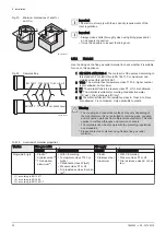
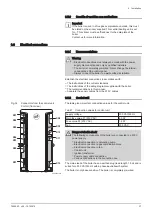
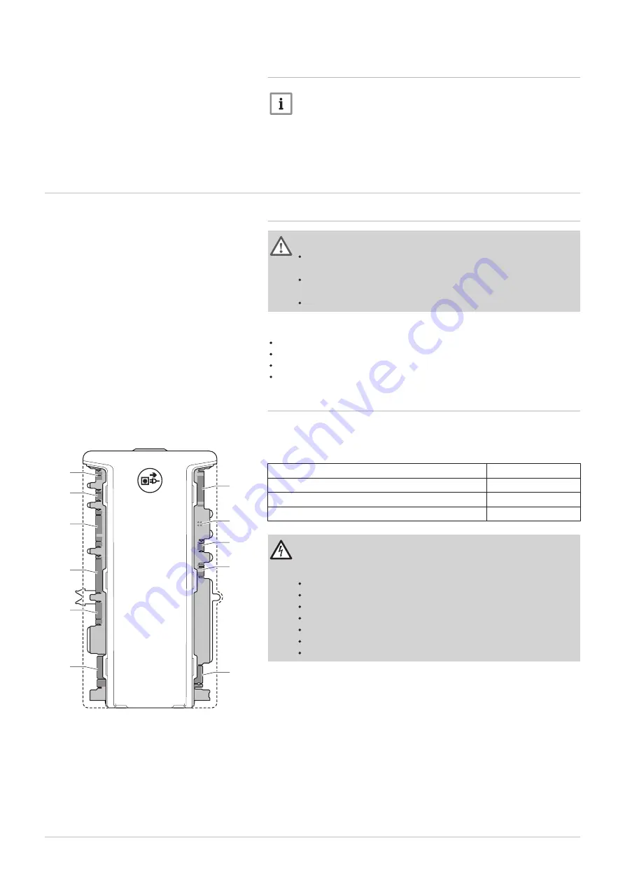
Fig.32
Connectors from the control unit
CU-GH (front view)
AD-0000915-01
X07
X08
X10
X09
X11
X12
X06
X05
X04
X03
X02
X01
6 Installation
7665063 - v.05 - 18102018
37

