19
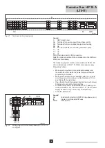
The following table indicates which jumpers need to be
FRQ¿JXUHGWRJHWKHUZLWKWKHDGGUHVVLQWKHGHYLFH
Unit
address
Jumper 1
position
Jumper 2
position
Jumper 3
position
Jumper 4
position
0
OFF
OFF
OFF
OFF
1
OFF
OFF
OFF
ON
2
OFF
OFF
ON
OFF
3
OFF
OFF
ON
ON
4
OFF
ON
OFF
OFF
5
OFF
ON
OFF
ON
6
OFF
ON
ON
OFF
7
OFF
ON
ON
ON
8
ON
OFF
OFF
OFF
9
ON
OFF
OFF
ON
10
ON
OFF
ON
OFF
11
ON
OFF
ON
ON
12
ON
ON
OFF
OFF
13
ON
ON
OFF
ON
14
ON
ON
ON
OFF
15
ON
ON
ON
ON
Table 04 Address table
6.4.5 LED signals for CAN-OT interface
If several faults occur simultaneously, the LED signalling
will display each fault in order of priority, until the problem is
resolved. The following list shows the order of priority. LED
status 0 has the highest priority.
LED on
No errors
OpenTherm and CAN-bus communication
working
/('ÀDVKHV
2x: No OpenTherm communication
3x: No CAN-bus communication
4x: Incorrect CAN-bus address settings
5x: Internal error
6x: CAN device is not supported
LED off
No voltage
Faulty
Table 05 LED signals for CAN-OT interface
6.4.6 Setting CAN-bus address on the Gas HP heat pump
In order to operate several heat pumps in a CAN-bus network
combined with CAN-OT interfaces, each heat pump must be
allocated a clear code. This can be done by setting parameter
40 in menu 5 for the heat pumps.
3DUDPHWHULVWKHSULQWHGFLUFXLWFRGHDQGLGHQWL¿HVWKH
device in the CAN network. Each heat pump is given a unique
code, independent of its position in the system. The value
that needs to be set for parameter 40 is the numerical code
assigned to the device and can vary from 0 to 478.
Set parameter 40 as follows:
1. Remove the front casing of the heat pump by unscrewing
and removing the screws.
2. Remove the cover plate of the electrical panel to be able to
access the set-up button.


