background image

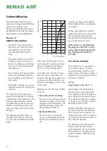
Device Description

The units are designed for univer-
sal and problem-free dehumidifica-
tion.  
Owing to their compact size, they 
are easy to transport and install.
The units operate according to the 
condensation principle and feature 
a hermetically sealed refrigeration 
system, low noise and mainte-
nance circulating fan, operating 
hour counter and connecting cable 
with plug.
Fully automatic electronic con-
trol, condensate container with 
integrated overflow protection 
(not with AMT 110-E) as well as 
connections for direct condensate 
removal ensure trouble-free con-
tinuous use.

The units comply with the fun-
damental safety and health re-
quirements of the permanent EU 
regulations.
The units are reliable and easy to 
operate.

unit applications

The units are used wherever 
dehumidication is necessary 
and consequential damage (e.g. 
through mould formation) is to be 
prevented. 

The units are also suitable for dry-
ing and dehumidification of: 

   New buildings, industrial build-

ings

   Cellar rooms, storage rooms

   Archives, laboratories

   Weekend homes,  

caravans

   Bathrooms, washrooms and 

changing rooms, etc.

As soon as the frost (ice) has de-
frosted and the temperature at the 
sensor rises again, the unit switch-
es back to normal dehumidification 
operation.

At a sufficiently high room tem-
perature, the gill surface is not cold 
enough for the formation of frost 
so that defrosting is unnecessary.  
This makes dehumidifiers particu-
larly economical in operation. 

At the condenser (heat exchang-
er), the cooled and dehumidified 
air is reheated and blown back into 
the room via the air outlet.  
The conditioned, drier and heated 
air mixes with the room air again.

Due to the constant circulation of 
the room air through the unit, the 
relative humidity in the room is 
gradually reduced to the required 
humidity (% R.H).

Depending on the room tem-
perature and humidity, only about 
30-40% of electrical energy is 
required depending on the unit 
cooling capacity.

Sequence of functions

The electronic control is activated 
when the unit is switched on.
The green pilot light in the switch 
illuminates.
Owing to automatic pressure 
equalisation, the units start with 
a delay of about 10 seconds and 
then operate in continuous duty.
The circulating fan sucks the moist 
room air via the dust filter, evapo-
rator and downstream condenser.
At the cold evaporator, heat is 
extracted from the room air and 
cooled to below the dew point. 
The water vapour contained in the 
room air deposits as condensate or 
frost on the evaporator fins.
When the temperature sensor 
measures a specific minimum value 
here, a timer is activated with a 
delay of 30 minutes.  
If during this time the evaporator 
temperature does not rise again, 
the cooling circuit is switched to 
hot gas defrost after the time has 
elapsed. 
During the defrost phase, the cir-
culating fan is off.

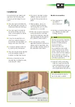
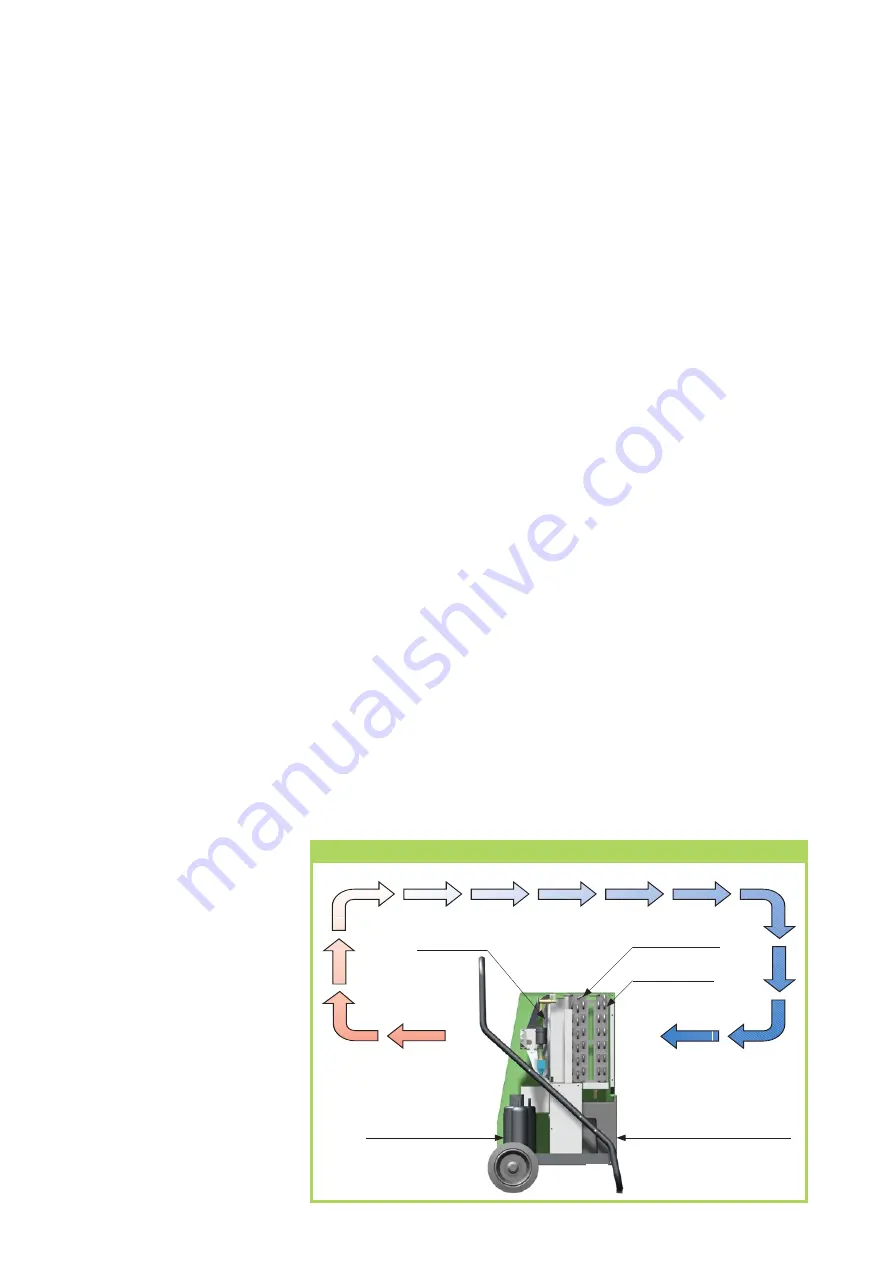
Diagram of the mode of operation of a REMKO dehumidifier

Condensate con-

tainer

Moist room air

Dehumidified

Room air

Compressor

Condenser

Evaporator

Fan

8

REMKO AMT

Summary of Contents for AMT 110-E

Page 1: ...Edition GB R12 REMKO AMT Dehumidifier Operation Technology Spare Parts...

Page 2: ......

Page 3: ...xcepted Dehumidification 4 Safety Instruction 6 Proper use 7 Customer Service and Warranty 7 Environmental Protection and Recycling 7 Equipment Description 8 Installation 9 Commissioning 10 Shutdown 1...

Page 4: ...rom buildings or materials is absorbed by the ambient air This increases their moisture content and ultimately results in corrosion mould rot peeling of paint coat ings and other unwanted moisture dam...

Page 5: ...fall below Building material and structures can absorb considerable amounts of water e g bricks 90 190 l m heavy concrete 140 190 l m sand lime bricks 180 270 l m The drying of moist materials e g ma...

Page 6: ...capacity but is rather de termined by the rate at which the material or parts of the building release their moisture Safety Instructions The units were subjected to ex tensive material functional and...

Page 7: ...on a wooden pallet if necessary The packaging materials are en vironmentally friendly and can be recycled With the reuse of packaging mate rial you make a valuable contribu tion to the reduction of w...

Page 8: ...makes dehumidifiers particu larly economical in operation At the condenser heat exchang er the cooled and dehumidified air is reheated and blown back into the room via the air outlet The conditioned...

Page 9: ...Room air circulation can be improved by installing the units raised about 1 metre The room to be dried or dehu midified must be closed with respect to the ambient atmos phere Open windows doors etc as...

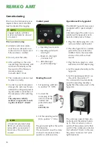
Page 10: ...nel 1 2 3 4 1 Operating hour counter 2 Operating switch with pilot light 3 YELLOW Pilot light Container full 4 RED Pilot light Fault Overheating Operation with a hygrostat The REMKO hygrostat accessor...

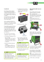
Page 11: ...er drips steadily or only during the defrost phases in the condensate trap or condensate container Via a connection not with AMT 40 E and 110 E the condensate flows into the condensate con tainer loca...

Page 12: ...ant C The water flows via a hose into a lower located drain This variant enables unsupervised continuous duty Condensate drain AMT 110 E AMT 110 E units are not provided with an internal condensate co...

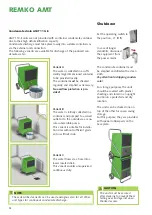
Page 13: ...d protective handle This can easily be removed if required The following must be observed for unit transport 1 Prior to a change of location switch off the unit and discon nect the mains plug from the...

Page 14: ...tor for pos sible icing frost formation If this is the case the automatic defrost function and tempera ture sensor must be checked If the unit does not operate cor rectly despite the checks carried ou...

Page 15: ...PE Steuerplatine C1 S C R PE NTC NTC Rot Gelb SW M1 M2 COMP FANMOTOR S1 AMT 40 E AMT 55 E to 110 E Electrical wiring diagram Test NTC NTC Rot only AMT 110 E T T T Test button The test button is only i...

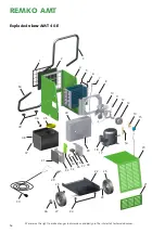
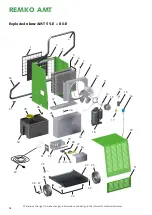
Page 16: ...hanges in dimensions and design in the interest of technical advances Exploded view AMT 40 E 4 5 6 8 10 11 12 13 14 15 2 1 16 17 20 21 26 27 22 25 25 30 29 32 33 35 34 38 37 36 39 40 45 46 47 49 50 23...

Page 17: ...plate 1105620 23 Wheelaxle 1105621 24 Rubber stopper supporting stand set 1105622 25 Wheel 1102155 26 Wheel cap 1101623 27 Circlip 1101622 29 Pull relief 1101267 30 Mains cable with plug 1105624 31 I...

Page 18: ...s in dimensions and design in the interest of technical advances Exploded view AMT 55 E 80 E 3 6 7 8 2 1 5 10 11 12 13 14 15 16 17 20 21 22 25 25 23 18 29 30 31 40 35 39 37 36 50 51 48 52 49 47 46 45...

Page 19: ...ion complete 1105646 1105671 21 End cover 1105647 1105647 22 Base plate 1105648 1105672 23 Wheelaxle 1105649 1105673 24 Rubber stopper base plate set 1105622 1105622 25 Wheel 1102155 1102155 26 Wheel...

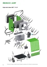
Page 20: ...e changes in dimensions and design in the interest of technical advances Exploded view AMT 110 E 3 2 1 16 17 18 19 10 5 4 6 7 8 9 11 15 24 25 22 20 26 29 27 31 35 29 30 47 46 44 43 42 37 41 38 40 39 2...

Page 21: ...19 Solenoid valve 1105669 20 Coil for solenoid valve 1105614 22 Compressor complete 1105688 24 Housing part inspection complete 1105689 25 End cover 1105690 26 Base plate 1105691 27 Wheelaxle 1105692...

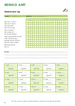
Page 22: ...18 Date Signature 19 Date Signature 20 Date Signature Remarks Model Model No 1 2 3 4 5 6 7 8 9 10 11 12 13 14 15 16 17 18 19 20 Clean unit surface Clean unit interior Clean fan blade Clean fan housin...

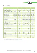
Page 23: ...tating piston Rotating piston Refrigerant R134a R407c R407c R407c Refrigerant quantity kg 0 31 0 55 0 65 1 55 Voltage supply V Hz 230 1 50 Max rated power consumption A 3 9 4 0 4 9 7 2 Max power consu...

Page 24: ...eing more than just a good reliable supplier REMKO a partner that helps solve problems Sales REMKO not only provides an extensive sales network in Germany and abroad but also unusually highly qualifie...

Reviews: