background image

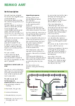
Electrical connection

   The units are operated

with 230 V / 50 Hz  
alternating current

   The electrical connection is 

made using a built-in mains 
cable with earthed safety plug

   Extensions 

to the connection cable 
may only be carried out by 
authorised electricians, subject 
to the length of the cable, 
connected load of the unit and 
taking into consideration how 
the unit is used at its location

Set-up

For the best economic and safe use 
of the units, the following notes 
must be followed in full:  

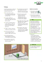
  The units must be set up 

in an upright and level position, 
to ensure that the condensate 
can drain freely

  To ensure optimum air 

circulation, the units should be 
set up in the centre of the room, 
where possible

  It must be ensured that the air 

can be sucked in on the front 
of the unit and blown out of 
the rear of the unit without 
obstruction

  Observe a minimum clearance 

of 50 cm from walls at all times

  Units must never be set up 

in the immediate vicinity of 
heaters or other sources of heat

  The room being dried or 

dehumidified must be closed 
to the neighbouring atmosphere

  Air circulation is improved if 

the unit is set up approx. 1 m 
above the ground 

  Avoid having opened windows 

and doors etc., and avoid 
frequent entry to or exit from 
the room as much as possible

  If the units are to be used 

in dusty environments, 
appropriate care and 
maintenance measures 
should be taken according 
to the relevant conditions 

  The output of the unit is entirely 

dependent on the conditions 
inside the room, room 
temperature, relative humidity 
and observance of the set-up 
instructions

   The units may not be used 

in environments containing 
a great deal of dust or chlorine, 
or in places with atmospheres 
containing ammonia

ATTENTION

All cable extensions must only 
be used in fully un-reeled or 
reeled off condition.

NOTE

The electrical connection 
to the units must be made 
at feedpoints with residual 
current devices in accordance 
with VDE 0100, Section 704. 
When installing the units 
in extremely damp 
environments such as laundry 
rooms, showers etc., the unit 
must secured with a residual 
current device provided 
by the customer in accordance 
with the regulations.

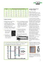
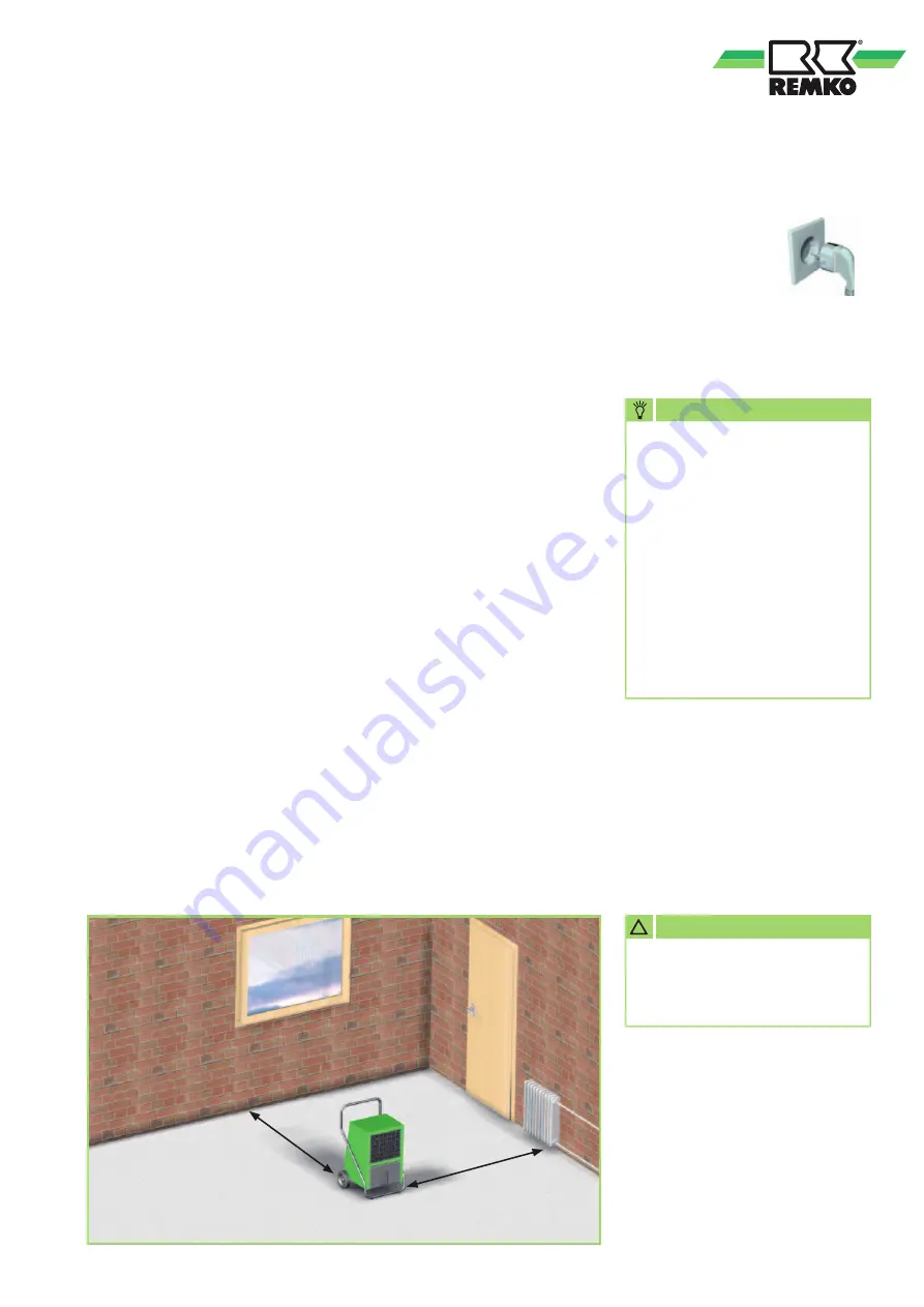
Wall clearance
min. 0.5 m

Maintain adequate clearance from 

heaters or other sources of heat.

Keep windows and doors closed!

!

9

Summary of Contents for AMT 115-E

Page 1: ...Edition GB D09 REMKO AMT Air dehumidifiers Operation Technology Spare parts REMKO AMT 45 E to 115 E...

Page 2: ......
Page 3: ...ts Air dehumidification 4 Safety notes 6 Intended use 7 Customer service and guarantee 7 Environmental protection and recycling 7 Unit description 8 Set up 9 Commissioning 10 Shutdown 12 Transportatio...

Page 4: ...isture water vapour released from parts of a building or materials is absorbed by the surrounding air As a result the moisture content increases which ultimately gives rise to corrosion mould rot peel...

Page 5: ...the dew point making it easier for the temperature to fall below it Building materials and structures are capable of absorbing considerable volumes of water such as brick 90 190 l m heavy concrete 140...

Page 6: ...quality inspections prior to delivery However dangers can result from the units if they are used improperly or not as intended by untrained personnel The following notes must be observed in full The...

Page 7: ...on a wooden pallet The packaging materials are environmentally friendly and can be recycled By recycling packaging materials you make a valuable contribution to the reduction of waste and conservation...

Page 8: ...d enough for rime formation to occur rendering defrosting unnecessary Therefore the air dehumidifiers work economically The cooled and dehumidified air is re heated by the condenser heat exchanger and...

Page 9: ...osed to the neighbouring atmosphere Air circulation is improved if the unit is set up approx 1 m above the ground Avoid having opened windows and doors etc and avoid frequent entry to or exit from the...

Page 10: ...mmissioning Control panel 1 2 3 4 1 Operating hours counter 2 Operating switch with Indicator light 3 YELLOW indicator light Container full 4 RED indicator light Malfunction overheating Operation with...

Page 11: ...tainer either continuously or only during the defrosting phases The condensate is fed into the condensate container below via a connection nozzle not AMT 45 E and AMT 115 E A float is located inside t...

Page 12: ...is fed into a lower drain via a hose pipe This variant enables unattended permanent operating mode AMT 115 E condensate drain Due to their high dehumidification capacity the AMT 115 E units are not eq...

Page 13: ...tion and protective clamp This can also be dismantled easily if required When transporting the units observe the following 1 Before each change of location switch off the unit and remove the power plu...

Page 14: ...ry Check the evaporator for ice or rime formation If ice has formed check the functionality of the automatic defrost and the temperature sensor If the unit fails to function correctly after the checks...

Page 15: ...riebs stunden F 3 15 A 1 0 A 2 1 4 3 2 1 4 3 Kondensatpumpe optional SCHWARZ WEISS VIOLETT VIOLETT Steckdose am Ger t Stecker F hler C Verdampfer Kondensator F hler Wasser Stop Lampe St rung Lampe Was...

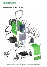
Page 16: ...ions and design as part of the ongoing technical development process Exploded view of the AMT 45 E unit 4 5 6 8 10 11 12 13 14 15 2 1 16 17 20 21 26 27 22 25 25 30 29 32 33 35 34 38 37 36 39 40 45 46...

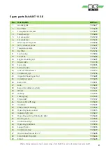
Page 17: ...909 18 Operating condenser 1105910 20 Inspection housing part cpl 1105618 21 Completion panel 1105619 22 Base plate 1105956 23 Axle 1105621 24 Base plate rubber stop set 1105622 25 Wheel 1102155 26 Hu...

Page 18: ...design as part of the ongoing technical development process Exploded view of the AMT 65 E and 85 E units 3 6 7 8 2 1 5 10 11 12 13 14 15 16 17 20 21 22 25 25 23 18 29 30 31 40 35 39 37 36 50 51 48 52...

Page 19: ...t cpl 1105671 1105671 21 Completion panel 1105647 1105647 22 Base plate 1105957 1105957 23 Axle 1105673 1105673 24 Base plate rubber stop set 1105622 1105622 25 Wheel 1102155 1102155 26 Hubcap 1101623...

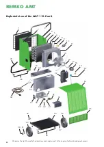
Page 20: ...ensions and design as part of the ongoing technical development process Exploded view of the AMT 115 E unit 3 2 1 16 17 18 19 10 5 4 6 7 8 9 11 15 24 25 22 20 26 29 27 31 35 29 30 47 46 44 43 42 37 41...

Page 21: ...enoid valve 1105715 20 Coil for solenoid valve 1105714 22 Compressor cpl 1105746 24 Inspection housing part cpl 1105689 25 Completion panel 1105690 26 Base plate 1105951 27 Axle 1105692 28 Base plate...

Page 22: ...te Signature 19 Date Signature 20 Date Signature Comments Unit type Unit number 1 2 3 4 5 6 7 8 9 10 11 12 13 14 15 16 17 18 19 20 Unit cleaned outside Unit cleaned inside Fan blade cleaned Fan housin...

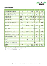
Page 23: ...Refrigerant quantity g 480 580 750 1270 Power supply V Hz 230 1 50 Max rated current consumption A 3 2 4 0 4 8 6 7 Max power consumption kW 0 730 0 890 1 020 1 385 at 20 C 70 RH kW 0 510 0 640 0 740...

Page 24: ...ust be advisers to our customers in air conditioning and heating technology Customer service Our units operate precisely and reliably However in the event of a malfunction REMKO customer service is qu...

Reviews: