10
Important information about mounting the revision
cover
◊
Make sure that the seals and revision cover are cor-
rectly placed.
◊
When mounting the revision cover, make sure the
fixing nuts are tightened evenly. Uneven tightening
of the fixing nuts may result in leakage.
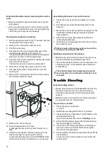
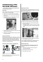
Cleaning the combustion chamber
1. Set the operating switch to the "0" position and pull
the plug from the mains socket.
2. Remove the combustion chamber cover.
3. Pull the burner plug.
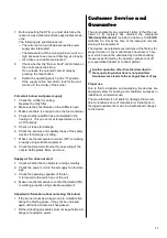
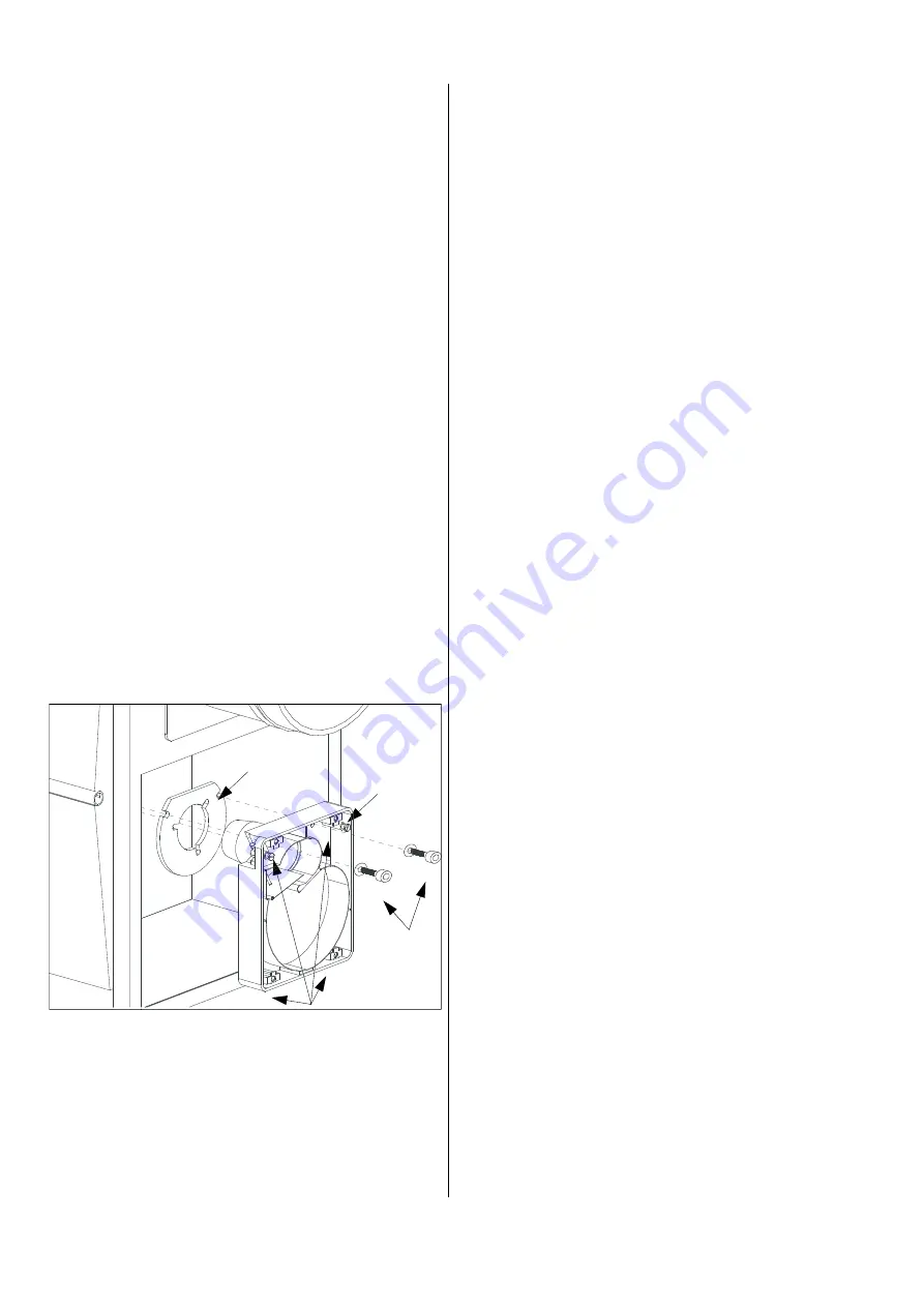
4. Unscrew the four quick-release fasteners of the
mounting base plate from the mount (1).
The quick-release fasteners and the mounting base
plate are not shown in the drawing below.
5. Carefully remove the complete mounting base plate
from the front of the unit.
The fuel line does not have to be dismantled.
6. Place the mounting base plate next to the unit.
7. Unscrew both cylinder head studs (2) from the
housing (3).
8. Remove the housing from the front of the combus-
tion chamber and set it aside.
Assembling the burner seal and the burner
1. Check the burner seal (4) and replace it if neces-
sary.
2. Push the burner seal onto the flame tube of the
housing.
3. Mount the burner seal (4) and the housing (3) to the
combustion chamber flange using both cylinder
head studs (2).
4. Attach the mounting base plate using the four
quick-release fasteners.
5. Insert the burner plug again and close the combus-
tion chamber cover.
Trouble Shooting
Important safety notices
◊
Repair work on the electrical installation and on the
forced-air oil burner may be carried out only by
authorised, expert personnel for safety-technical
reasons.
◊
Before all work on the device, the mains plug must
be removed from the mains socket.
The unit does not start
1. Check the mains connection.
1~ 230 V.
2. Switch the operating switch to the "I" position.
3. Check whether the "Operation" control lamp on the
control panel has lit up.
It must indicate that the unit is in "Heating" mode.
4. Check that the jumper plug or the thermostat plug
has been plugged in correctly.
5. Check the room thermostat setting. The tempera-
ture set on the room thermostat must be higher
than the room temperature.
6. Check whether the safety temperature limiter (STB)
has activated.
You must remove the protective cover next to the
control panel.
After all work on the device, perform an electrical
safety test according to VDE 0701.
Additional maintenance information
◊
Maintenance work on the forced-air oil burner may
only be performed by authorised personnel.
◊
The exhaust emission limits must be observed in ac-
cordance with §11 of the small furnace ordinance
(1. BImSchV).
9. Remove the burner seal (4).
10. Do not damage the burner seal.
A damaged burner seal may lead to faulty air in-
take.
11. Clean the combustion chamber using a vacuum
cleaner through the opening of the burner.
A special boiler cleaning set for the REMKO indus-
trial vacuum cleaner is available as an accessory.
The exhaust emission analysis may be perfo-
med only when the combustion chamber cover
is closed.
1
2
3
4
Summary of Contents for CLK 20
Page 2: ......


