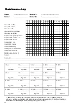
background image

18 

Maintenance Log


  1  2  3  4  5  6  7  8  9  10  11  12  13  14  15  16  17  18  19  20 

Clean unit – surface 

Clean unit – interior 

Clean fan blade 

Clean combustion chamber 

Clean heat exchanger 

Replace waste gas suppressors 

Replace seals - revision cover 

Replace seals - burner 

Replace filter - fuel 

Check safety devices 

Check electric safety 

Check protective mechanisms 

Check unit for damage 

Maintenance – burner 

*

Test run 


Model 

: ................................ 

Model No. 

: ......................................


Burner 

: ................................ 

Burner No. 

: ......................................


*

)  Maintenance work may be performed on the forced-air oil burner only by authorised expert 

personnel; settings and adjustments must comply with the legal regulations (1. BImSchV. (German 
Air Pollution Control Act)). A corresponding test log must be kept.


Comments:.................................................................................................................................................................... 

...................................................................................................................................................................................... 

1. Date: 


2. Date: .....................   3. Date: .....................   4. Date: .....................   5. Date: 


..................................   ..................................   ..................................    


Signature 

Signature 

Signature 

Signature 

Signature 

6. Date: 


7. Date: .....................   8. Date: .....................   9. Date: .....................   10. Date: 


..................................   ..................................   ..................................    


Signature 

Signature 

Signature 

Signature 

Signature 

11. Date: 


12. Date: ...................   13. Date: ...................   14. Date: ...................   15. Date: 


..................................   ..................................   ..................................    


Signature 

Signature 

Signature 

Signature 

Signature 

16. Date: 


17. Date: ...................   18. Date: ...................   19. Date: ...................   20. Date: 


..................................   ..................................   ..................................    


Signature 

Signature 

Signature 

Signature 

Signature 

Summary of Contents for CLK 20

Page 1: ...REMKO powerful like a bear REMKO CLK 20 Mobile Heaters Edition GB M08 Operation Technology Spare Parts ...

Page 2: ......

Page 3: ...14 Spare Parts List 15 Commissioning of Forced Air Oil Burner 16 Maintenance Log 18 EC Declaration of Conformity 19 Always keep these operating instructions in the direct vicinity of the installation site or unit Before commissioning use of the equipment these operating instructions must be read carefully Our guarantee becomes null and void if the unit is used set up or maintained improperly or if...

Page 4: ... operated with a separate forced air oil burner The units are equipped with an electrical oil preheater via the nozzle stock The units are equipped with a low noise maintenance free high performance axial ventilator a room thermo stat socket a connection cable with a plug and a drum fitting The units correspond with the basic safety and health requirements of all pertinent EU regulations and are e...

Page 5: ...e shut down 55 Rule infringements Whoever violates the regulations of VBG 43 whether deliberately or due to negligence is acting contrary to Monitoring unit operation All functions of the unit are fully automatic and moni tored for safety by the safety devices and the automatic burner relay part of the forced air oil burner If the flame burns irregularly or goes out the unit is switched off by the...

Page 6: ...Due to the operation of the equipment no dangers or unreasonable nuisances may arise The equipment operator must guarantee that unau thorised persons cannot manipulate the equipment or the energy supply Because rain and snow can be pulled in through the supply air fan a suitable protective covering should be used Heating rooms The equipment may be used for room heating only with a room thermostat ...

Page 7: ...vice on a stable surface Guarantee a sufficient combustion air supply Make sure the air intake and outlet is unobstructed Avoid overpressure and underpressure in the room where the unit has been installed Make sure that enough fuel is supplied Use only clean EL heating oil or diesel Do not use biodiesel Additional information The exhaust emission specifications of the forced air oil burner must be...

Page 8: ...eferably take place using the on site outlet nozzle If necessary pipes or special hot air tubes or foil hoses for air distribution in the possible area of fan output observe the channel resistance equipment compres sion Use only hot air tubes accessories approved by Remko In the process pay attention to the air direc tion To prevent heat from building up the pipes and tubes may not have sharp kink...

Page 9: ...the fuel filter for soiling at regular intervals Dirty filters must be replaced Check the unit for mechanical damage and have de fective parts replaced by an expert Check the fan blades and combustion chamber with the heat exchanger for soiling at regular intervals and clean them when necessary Check on site oil tanks for soiling and foreign bodies regularly and clean them when necessary Always ma...

Page 10: ...portant safety notices Repair work on the electrical installation and on the forced air oil burner may be carried out only by authorised expert personnel for safety technical reasons Before all work on the device the mains plug must be removed from the mains socket The unit does not start 1 Check the mains connection 1 230 V 2 Switch the operating switch to the I position 3 Check whether the Opera...

Page 11: ... air burner and power supply 1 Check the oil filter for soiling Replace the dirty filter 2 Make sure the shut off valve on the oil filter is open 3 Make sure there is enough fuel in the fuel container 4 Check whether paraffin has accumulated in the heating oil This can occur at temperatures as low as 5 C already 5 Check oil tubes for damage 6 Check the sensors and capillary tubes of the safety dev...

Page 12: ...current fan A 0 6 Operating capacitor of the fan µF 3 Fuse protection on site A 10 Temperature increase t K 41 Sound pressure level LpA 1m 3 dB A 60 Air outlet ø mm 300 Chimney adapter Ø mm 130 Total unit length mm 1 180 Total unit width with wheel attachment mm 510 580 Total unit height with wheel attachment mm 735 880 Weight with forced air oil burner kg 94 2 The listed nozzle sizes and pump pre...

Page 13: ... C Capacitor S1 Operating switch H1 Control lamp green S2 Reset button burner H2 External control lamp red STB Safety temperature limiter KL Terminal strip TR Temperature control thermostat M Fan motor TW Temperature monitor RT Thermostat socket WS Burner plug 7 pole We reserve the right to make changes in dimensions and design in the interest of technical advances Brown Orange Black Blue ...

Page 14: ...make changes in dimensions and design in the interest of technical advances 65 1 50 2 49 48 55 45 4 19 35 32 33 36 39 38 37 63 18 56 60 11 57 57 66 67 68 69 70 71 72 8 17 27 30 29 28 64 STB sensor TW sensor TR sensor 5 3 6 7 9 10 26 16 15 47 34 61 View of control panel ...

Page 15: ...t cover 1104907 34 Lock for burner compartment cover 1104908 35 Support base 1104910 36 Axle 1104911 37 Wheel 1101621 38 Wheel cap 1101623 39 Circlip 1101622 45 Combustion chamber complete 1104912 47 Waste gas suppressor set 1104913 48 Revision cover 1104914 49 Seal for revision cover 1104915 50 Rosette for chimney connection 1104916 55 Transport handle front 1104917 56 Transport handle rear 11049...

Page 16: ...e and baffle plate All dimensions are approx values in mm D E 4 5 4 3 Mounting base plate After the ignition electrode baffle plate and air inlet nozzle are adjusted the mounting base plate is re mounted 1 Attach the mounting base plate using the four quick release fasteners 2 Mount the fuel line to the burner 3 Reinsert the burner plug Adjusting the air flap Adjust the air flap using the adjustin...

Page 17: ...ncrease pressure Counterclockwise Reduce pressure 5 After making the pressure setting secure the adjust ing screw using the counter nut 5 Measuring the combustion gases Every stationary combustion plant must be checked by measuring the exhaust emission values according to the first Bundesimmissionsschutzverordnung 1 BImSchV German Air Pollution Act The owner is obliged to have the combustion plant...

Page 18: ... Burner No Maintenance work may be performed on the forced air oil burner only by authorised expert personnel settings and adjustments must comply with the legal regulations 1 BImSchV German Air Pollution Control Act A corresponding test log must be kept Comments 1 Date 2 Date 3 Date 4 Date 5 Date Signature Signature Signature Signature Signature 6 Date 7 Date 8 Date 9 Date 10 Date Signature Signa...

Page 19: ...e of manufacturer REMKO GmbH Co KG Air Conditioning and Heating Technology Im Seelenkamp 12 32791 Lage Germany Unit machine design Mobile hot air heater for operation with a separate forced air burner Series REMKO CLK 20 Serial number 594 Valid regulations MA RL 89 392 EEC Machinery Directive 98 37 EC NS RL 73 23 EEC Low Voltage Directive EMC RL 89 336 EEC EMC Directive Applied standards EN 292 1 ...

Page 20: ...REMKO GmbH Co KG Air Conditioning and Heating Technology Im Seelenkamp 12 32791 Lage Germany P O Box 1827 32777 Lage Germany Phone 49 5232 606 0 Fax 49 5232 606 260 ...

Reviews: