background image

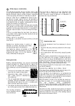
Automatic defrost


The  humidity  contained  in  the  ambient  air  condenses 
when cooled and covers the evaporator fins with frost or 
ice  depending  on  the  air  temperature  and  the  relative 
humidity.  This  frost  or  ice  buildup  is  automatically  de-
frosted from the unit. 

During the defrost phase, the dehumidification mode is 
briefly  interrupted.  The  “Defrost”  control  light  indicates 
that the defrost cycle is switched on. 

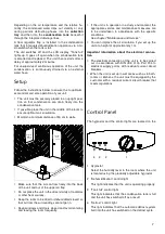
Emptying the condensation tank 

1.  Carefully  pull  out  the  tank  to-

wards you. 

2.  Pour  the  condensation  into  a 

drain. 

3.  Clean the tank with a clean towel. 

4.  Carefully reinsert the tank into the unit. 

5.  Keep in mind that the unit only starts when the tank 

has been correctly inserted. 


The red warning lamp (Tank full) will go out and au-
tomatic operation will continue.


Shutting Down the Unit 

Turn  the  knob  of  the  hygrostat  to  the 
“OFF” position. 

Cleaning the Filter


To prevent damage to the unit, it is equipped with an air 
intake filter. 

The  air  intake  filter  must  be  inspected  as  necessary, 
however,  at  least  every  two  weeks,  and  cleaned  if  re-
quired  to  prevent  its  performance  from  suffering  or 

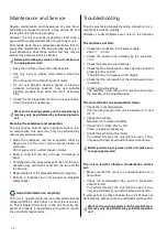
Continuous  operation  with  an  external  condensa-
tion hose. 

The  unit  must  be  equipped  with  a  connection  adapter 
on the left side. A standard 

1

/

2

" water hose can be con-

nected here. 

Make  sure  that  the  hose  is  placed  at  an  incline  to 
the  drain  so  that  the  condensation  is  not  blocked 
from flowing out of the condensation tank! 


1.  Using  a  suitable  tool,  break  the 

cover F of the connection adapter 
from the unit wall. 


Only  necessary  for  the  initial 
connection.


2.  Connect  a  drainage  hose  that  is 

sufficiently long to the connection 
adapter. 

When the unit is in continuous operation, the condensa-
tion  can  now  be  directed,  for  example,  to  a  drain  at  a 
lower level. 

Unit transport 

The unit is equipped with wheels and a handle to make 
it easy to transport. 


Prior  to  moving  the  unit,  switch  the  unit  off  and  un-
plug it. 


Then empty the condensation tank. 


Watch out for condensation that drips out.


Do not use the power cord to pull the unit. 

Prior to longer periods of non-operation


1.  Unplug the power cord. 

2.  Empty the condensation tank and dry it with a clean 

towel. 


Watch out for condensation that drips out.


3.  Follow the instructions for cleaning the air intake fil-

ter.


4.  To prevent dust from getting inside the unit, protect it 

with, for example, a plastic cover. 

5.  Store the unit in an upright position in a location pro-

tected from dust and direct sunlight. 

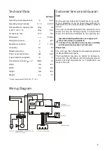
1.  Switch the unit off by pressing the 

“On/Off” button. 

2.  Reach into the opening G and pull 

the air intake filter out of the unit. 

3.  Clean  the  air  intake  filter  with 

warm  water  or  with  a  vacuum 
cleaner.


4.  Remove  heavy  dirt  by  rinsing  the 

unit in a soapy solution at a maxi-
mum temperature of 40 °C.   

Then rinse with clean water. 

5.  Keep in mind that the air intake fil-

ter may not be damaged and must 
be completely dry before being re-
placed  to  prevent  damage  to  the 
unit. 

The unit may never be operated without the air in-
take filter!  


Summary of Contents for ETF 240

Page 1: ...REMKO ETF 240 Portable Air Dehumidifier Edition GB S10 Operation Technology REMKO powerful like a bear...

Page 2: ......

Page 3: ...ions Portable air dehumidifier REMKO ETF 240 Contents Page Air Dehumidification 4 Safety Instructions 6 Description of the Unit 6 Setup 7 Control Panel 7 Initial Operation 8 Shutting Down the Unit 9 C...

Page 4: ...percentage of water is indicated in g per kg of dry air absolute water content 1 m of air weighs approx 1 2 kg at 20 C Depending on the temperature each kg of air can only absorb a defined quantity o...

Page 5: ...ergy is released when gas is lique fied and this energy is called condensation heat The energy produced from evaporation and condensa tion heat is identical For water this is 2250 kJ kg 4 18 kJ 1kcal...

Page 6: ...ume no liability and the guarantee becomes null and void Work on the cooling system and the electrical sys tem may only be performed by authorised person nel Description of the Unit The unit has been...

Page 7: ...The unit must be securely placed in an upright posi tion so that condensation can drain freely into the condensation tank If possible place the unit in the middle of the room to ensure optimum air cir...

Page 8: ...rds You can adjust the direction of the air any way you want Hygrostat setting for the recommended humidity in residences Approx 50 Hygrostat setting for the recommended humidity in archives Approx 40...

Page 9: ...wing out of the condensation tank 1 Using a suitable tool break the cover F of the connection adapter from the unit wall Only necessary for the initial connection 2 Connect a drainage hose that is suf...

Page 10: ...erly in accordance with general regula tions and local requirements Import information on recycling Work on the cooling system and the electrical sys tem may only be performed by authorised person nel...

Page 11: ...xclusively for dehumidification purposes The manufacturer assumes no liability for damage re sulting from non compliance with manufacturer specifi cations and legal requirements or if modifications ar...

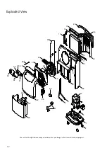
Page 12: ...6 5 8 9 10 11 17 19 21 22 25 28 30 35 33 31 39 38 40 41 42 44 46 49 51 47 48 20 29 36 32 Exploded View We reserve the right to make changes to dimensions and design in the interest of technical progr...

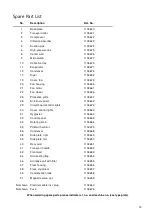
Page 13: ...r 1103642 29 Circuit board control lights 1103674 30 Cover control lights 1103663 31 Hygrostat 1103664 32 Control panel 1103665 33 Rotating knob 1103666 35 PCB with control 1103675 36 Condensor 110366...

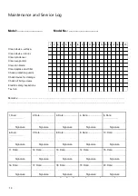
Page 14: ...13 14 15 16 17 18 19 20 Model Model No The unit must be maintained according to legal regulations by authorised personnel only Remarks 1 Date 2 Date 3 Date 4 Date 5 Date Signature Signature Signature...

Page 15: ......

Page 16: ...REMKO GmbH Co KG Klima und W rmetechnik 32791 Lage Im Seelenkamp 12 32777 Lage PO Box 1827 Phone 49 5232 606 0 Fax 49 5232 606 260 E mail info remko de Internet www remko de...

Reviews: