background image

Troubleshooting

The units are manufactured 
using state-of-the-art production 
methods and tested several times 
to verify their correct function. 
However, if a functional fault 
should occur, the unit should first 
be checked in accordance with the 
following list.

The unit does not start

  Check the setting of 

the operating switch. The green 
indicator light should illuminate

  Check power supply 

220-240 V/1~/50 Hz

  Check the power plug and 

the cable for damage

  Check the customer-provided 

mains protection. 
Minimum protection 10A

  Check the level and correct 

positioning of the condensate 
container. 
The front sealing flap must be 
fully closed and locked

  Check the function of 

the microswitch

  Check the setting of 

the humidity switch 
(accessories).  
The pre-set value must be 
lower than the relative humidity 
in the room

  Check the humidity switch 

adapter for damage and correct 
positioning 

The unit runs but does not 
form any condensate

  Check the room temperature.

The operating range of the unit 
is between 3°C and 32°C 

  Check the air humidity, at least 

40 % RH is required

  Check the setting of 

the humidity switch, set a lower 
humidity value if necessary

  Check the dust filter for 

contamination and clean or 
replace if necessary

  Check the evaporator 

and condenser fins for 
contamination and clean if 
necessary 

  Check the evaporator for ice 

or rime formation. If ice has 
formed, check the functionality 
of the automatic defrost and 
the temperature sensor 

  Check whether or not 

the evaporator temperature is 
below room temperature. If this is 
not the case, check the automatic 
defrost or room temperature

The unit does not start

  Check whether or not the 

condensate container is inserted 
correctly and that the front 
sealing flap is locked

  Check whether or not mains 

power is available

CAUTION

Work on the refrigerant 
system and on the electrical 
equipment must only be 
conducted by a specially 
authorised specialist! 

CAUTION

An electrical safety check must 
be carried out in accordance 
with VDE 0701 after any work 
on the units.

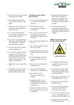
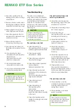
4.  Clean the condenser fins by 

blowing, with suction or using a 
smooth brush. 

5.  Exercise extreme caution when 

cleaning the condenser. The fine 
aluminium fins bend very easily.

6.  Never subject to sharp jets of 

water (high-pressure cleaners).

7.  Clean the evaporator fins, for 

example with a lukewarm soap 
solution (or similar).

8.  Rinse with clean water to 

remove any remaining soap.

9.  Clean the internal surfaces of 

the entire unit as well as the fan 
blade.

10.  Once cleaning has been 

completed, the unit should be 
dried with care.  

Take particular care with 
electrical components!

11.  Re-install all dismantled 

components in reverse order. 

12.  Carry out a unit function check 

and electrical safety check. 

NOTE

If the unit fails to function 
correctly after the checks have 
been carried out, contact an 
authorised specialist.

20

REMKO ETF Eco Series

Summary of Contents for ETF 500 Eco

Page 1: ...Operating and installation instructions Edition EN X02 Read the instructions prior to performing any task ETF 500 Eco ETF 600 Eco REMKO ETF Eco series Mobile air dehumidifiers...

Page 2: ......

Page 3: ...to modifications No liability accepted for errors or misprints Air dehumidification 4 6 Safety notes 6 12 Intended use 13 Customer service and guarantee 13 Environmental protection and recycling 13 Un...

Page 4: ...leased from parts of a building or materials is absorbed by the surrounding air As a result the moisture content increases which ultimately gives rise to corrosion mould rot peeling of paint and other...

Page 5: ...condenses and is collected in a condensate trap from where it is drained off Drying materials Water vapour condensation Because the capacity for the maximum possible volume of water vapour increases a...

Page 6: ...s its moisture Safety notes General safety notes Carefully read the manual before commissioning the units or their components for the first time It provides useful tips and notes such as hazard warnin...

Page 7: ...An unobstructed air inlet and air outlet must be guaranteed at all times The air inlet grille must always be kept free of dirt and loose objects The units must not be covered during operation The unit...

Page 8: ...close to the unit For safety reasons people with mental physical or other health limitations must not operate this unit unattended The unit is not permitted to be operated with damaged cables The unit...

Page 9: ...t all times Work may only be car ried out by authorised specialist personnel with knowledge of handling combustible refriger ants Prepare the work area Any persons present must be informed about the r...

Page 10: ...e guaranteed again If the defect on the spare part cannot be remedied and downtime of the unit is no longer acceptable an adequate temporary solution must be arranged The owner operator of the unit mu...

Page 11: ...refrigerant or if possible the affected part disconnected from the system using stopcocks The affected system parts must be flushed with oxygen free nitrogen run before and during the repair work Emp...

Page 12: ...ant Transportation of units which contain combustible refriger ants National provisions must be observed Storing of units which contain combustible refrigerant National provisions must be observed Tra...

Page 13: ...packaging materials are environmentally friendly and can be recycled By recycling packaging materials you make a valuable contribution to the reduction of waste and conservation of raw materials Ther...

Page 14: ...ough for rime formation to occur rendering defrosting unnecessary Therefore the air dehumidifiers work economically The cooled and dehumidified air is re heated by the condenser heat exchanger and blo...

Page 15: ...ources of heat Air circulation is improved if the unit is set up approx 1 m above the ground The room being dried or dehumidified must be closed to the neighbouring atmosphere Avoid having opened wind...

Page 16: ...on with a humidity switch The REMKO humidity switch accessories is supplied with a special adapter The following procedure must be followed when commissioning units in conjunction with a humidity swit...

Page 17: ...dehumidification mode The unit will switch off and the yellow indicator light will illuminate To empty the condensate container the following procedure must be followed 1 Move the operating switch 2 t...

Page 18: ...er 3 If moisture remains on the evaporator or water remains in the condensate container the units must only be transported in an upright position 5 Drain the condensate into a lower level drain To ope...

Page 19: ...y be operated with the dust filter in place Observe the regular care and maintenance intervals In accordance with the operating conditions the units must if necessary be checked at least yearly by a s...

Page 20: ...for ice or rime formation If ice has formed check the functionality of the automatic defrost and the temperature sensor Check whether or not the evaporator temperature is below room temperature If thi...

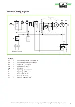
Page 21: ...iner full H2 Control lamp green in operation K1 Time relay t 30 min M1 Compressor motor M2 Fan motor P1 Operating hours counter S1 Operating switch S2 Microswitch float S3 Defrost thermostat Y1 Defros...

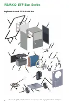
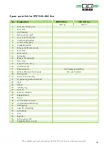
Page 22: ...imensions and design as part of the ongoing technical development process Exploded view of ETF 500 600 Eco 4 5 6 8 10 11 12 13 14 15 2 1 16 17 20 21 26 27 22 25 30 29 32 33 35 34 37 36 23 23 7 24 18 3...

Page 23: ...Socket for time relay 16 Condenser cpl 17 Solenoid valve On request by providing 18 Defrost thermostat with probe the serial number 19 Microswitch 20 Mains cable with plug 21 Cable passage with strain...

Page 24: ...gnature 19 Date Signature 20 Date Signature Comments Unit type Unit number 1 2 3 4 5 6 7 8 9 10 11 12 13 14 15 16 17 18 19 20 Unit cleaned outside Unit cleaned inside Fan blade cleaned Fan housing cle...

Page 25: ...0 Max rated current consumption A 2 71 2 90 Max power consumption kW 0 62 0 67 At 20 C 70 RH kW 0 49 0 50 Specific energy consumpt SEC max kWh l 0 31 0 26 At 20 C 70 RH kWh l 0 26 0 20 Electrical prot...

Page 26: ...26 REMKO ETF Eco Series...

Page 27: ...27...

Page 28: ...5232 606 260 E mail info remko de URL www remko de REMKO GmbH Co KG Klima und W rmetechnik Im Seelenkamp 12 32791 Lage Hotline within Germany 49 0 5232 606 0 Hotline International 49 0 5232 606 130 W...

Reviews: