+
+
M
~
M
~
L1 N
PE
h
aC
Kompressor
S2
H1
H2
S3
M1
M2
Y1
P1
S1
K1
230V 50Hz
2
3
1
H
C
R
S
C
7
6
5
2
8
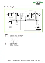
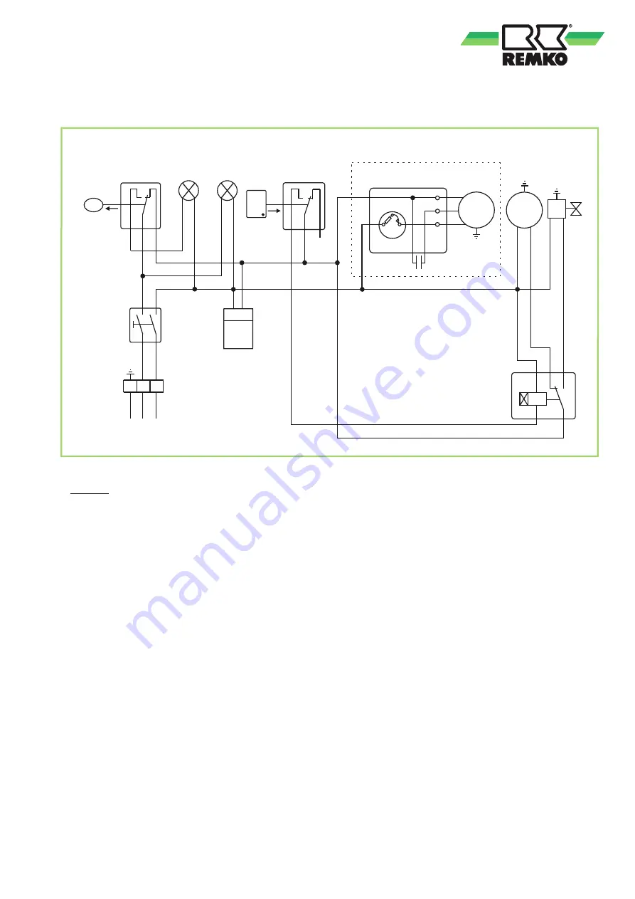
Electrical wiring diagram
Legend:
H1
=
Control lamp (yellow = container full)
H2
=
Control lamp (green = in operation)
K1
=
Time relay (t = 30 min.)
M1
=
Compressor motor
M2
=
Fan motor
P1
=
Operating hours counter
S1
=
Operating switch
S2
=
Microswitch (float)
S3
=
Defrost - thermostat
Y1
=
Defrost - solenoid valve
We reserve the right to modify the dimensions and design as part of the ongoing technical development process.
Compressor
220-240 V/50 Hz
21

