5
Before using for the first time
■
The correct unit setup and as-
sembly of any accessories used
must be checked.
Switching on the device
■
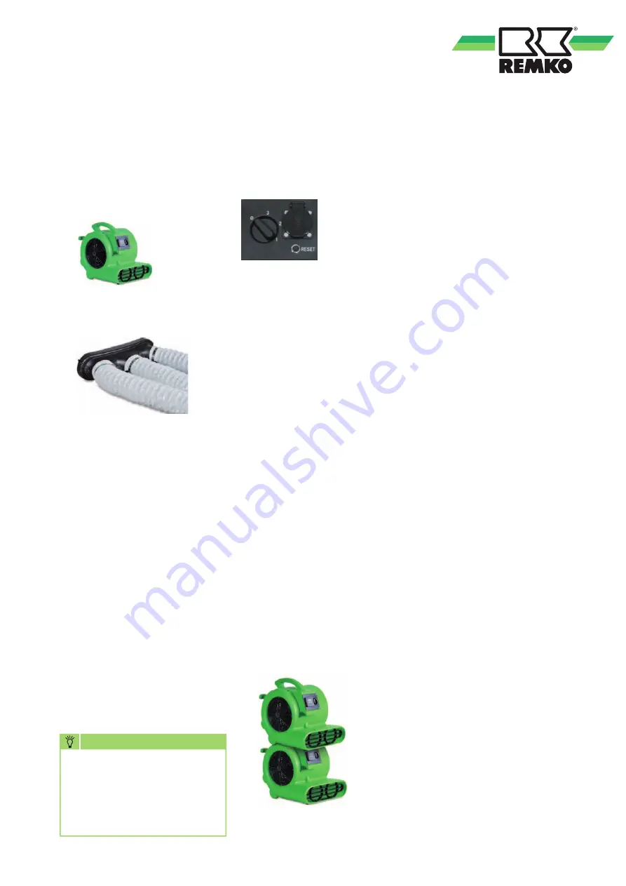
Switch the unit to the desired
power level using the 3-speed
selector switch.
Commissioning
NOTE
Electrical connection of the
units must be made at a
separate supply point using
a residual-current-operated
circuit-breaker according to
VDE 0100 § 55.
Decommissioning
Care and maintenance
The units are virtually mainte-
nance-free in normal operation.
To ensure trouble-free operation,
however, they should be inspected
regularly and cleaned and/or
repaired if necessary according to
the respective conditions for use.
Cleaning the units
■
The units must be disconnected
from the supply in all poles and
locked to prevent unauthorised
reconnection.
■
The protective grids for the air
inlets must be cleaned regularly
and replaced in case of dam-
age.
■
Clean all air inlets and air outlet
louvres.
■
Remove the protective grid
before cleaning the fan cylinder.
■
Remove heavy soiling on the
fan and fan housing with a
soap solution.
■
The units must be cleaned only
dry or with a moist cloth and a
small amount of soap solution if
necessary.
■
Under no circumstances use
high-pressure cleaners or steam
jet equipment.
■
Do not use caustic cleaning
agents or cleaning agents con-
taining solvents.
■
Avoid causing damage when
using compressed air.
■
Set the operating switch to the
“0” position.
■
Read the operating hours coun-
ter.
For extended periods of non-
use:
■
Disconnect the unit from the
mains supply.
■
Clean the unit and store it in a
dry location, free of dust and
direct sunlight.
Electrical connection
■
The 230V electrical connection
is implemented using a fitted
mains cable with safety plug.
■
Connect the mains plug with a
properly installed and secured
mains socket.
■
All cable extensions must only
be used uncoiled or unwound.
Free-blowing unit, directly above
the ground
Optional air distributor head #
1009530
with 3 x 10m WL tube
#
1009532
ATTENTION!
Always
attach the tubes with suit-
able straps or clamps.
Example 1:
Example 2, only for RTV 30:
■
The RTV 30 unit has either an
operating hours counter or an
additional 230V / 10A socket.
■
When required, read the oper-
ating hours counter and note
down the reading.
The RTV 30 unit can be stacked
for space-saving storage.
Fig.: Control panel with
RTV 30 operating
switch
and additional socket
Summary of Contents for RTV 15
Page 2: ...2 ...


