Installation material
The unit is fastened on vibration
dampers (accessories) to the
floor by means of bolts. The
carrying capacity of the bracket
and the wall must be taken into
account when fastening to the
wall.
Definition of the Danger Area
Access to the unit is only permitted
for authorised and trained persons.
If unauthorised persons can
approach the danger areas, these
areas must be identified with
corresponding signs, barriers, etc.
■
The external danger area
surrounds the unit up to a
distance of 2 m, measured
in all directions from the unit
housing.
■
The external danger area on-
site can differ as a result of the
setup. The specialist company
performing the installation work
bears the responsibility for this.
■
The internal danger area is
located inside the machine
and can only be reached with
the use of an appropriate
tool. Access is prohibited for
unauthorised persons!
Installation
NOTE
Installation should only be
performed by authorised
specialists.
Unit installation
1. Install the vibration dampers
(accessories) under the unit
(accessories)
2. Attach the unit to the building
where structurally permitted.
Refer to the Selecting the
installation location
chapter for
this.
3. When installing the unit,
ensure that the minimum
clearances described hereafter
are complied with. Any
infringement of these stipulated
clearances can result in
a functional impairment of
the unit operation.
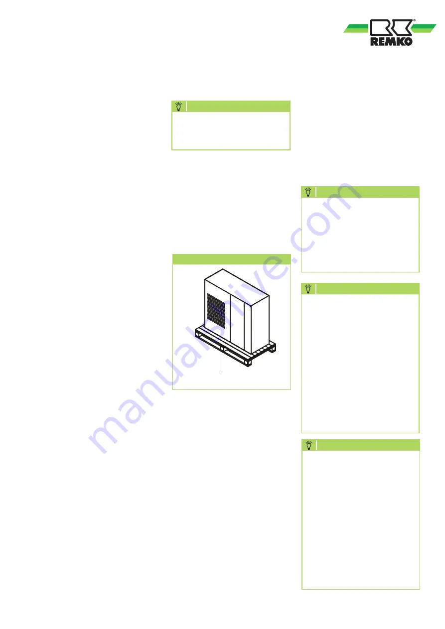
Disassembly of the transport
pallets
The units are supplied with
transport pallets for the purpose
of transportation. Remove these
before installation.
Transport packaging
Transport pallet
4. Ensure that structure-borne
sound is not transferred to parts
of the building.
5. Connect the medium pipings.
6. Connect the unit electrically.
NOTE
The electrical connection of
the unit is to be established by
suitable specialist personnel and
in compliance with all electrical
safety regulations. Compliance
with VDE regulations is
essential.
NOTE
The dimensioning of the supply
line and the selection of the
customer-side unit safeguard(s)
is the responsibility of the
specialist company carrying out
the work. The unit manufacturer
provides no information
regarding the dimensioning
of pipework or the selection
of fuses/breakers as these are
subject to local conditions.
All of the data required for
the selection can be found in
the technical data for the unit.
NOTE
The selection of the RCD
breaker is the responsibility
of the specialist company
carrying out the work. Based on
the provisions per VDE 0160,
E VDE 0100 Part 530 as well
as the guidelines of VdS 3501
and the safety regulations from
BGI 608, the use of an AC/
DC-sensitive, type-B RCD is
recommended for ensuring
standards-compliant personnel
and fire protection.
21


