background image

Fan control

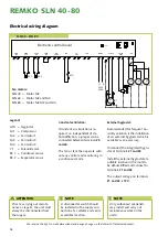
When the hygrostat starts the 
dehumidifier, the fan(s) is/are 
switched on together with the 
compressor.

If constant ventilation is required, 
i.e. independent of dehumidifica-
tion, a jumper can be connected 
between terminals 25 and 26.

The fan or fans then operate in a 
continuous mode.

Defrosting

At room temperatures below 20°C, 
the evaporator will start to frost 
after a short time.
When the evaporator sensor 
registers a temperature below 5°C 
on the evaporator surface, the unit 
continues to operate for 30 min-
utes in dehumidification mode.  
After lapse of this time, the com-
pressor stops and passive defrost-
ing starts in that the fan or fans 
slowly blow room air over the 
evaporator and gradually defrost 
the same in the process.  
When the evaporator sensor regis-
ters a temperature above 5°C, the 
compressor is switched on again.

Safety circuit

If the temperature at the conden-
ser should exceed 55°C (e.g. due 
to fan failure or excessive room 
temperature (above 36°C)), the 
compressor automatically stops to 
avoid being overloaded.  
The compressor restarts automati-
cally after 45 minutes. 

The drop symbol in the display 
flashes!

  Observe regular care and main-

tenance intervals.

   Depending on the particular 

operating conditions, the units 
should be tested by an expert 
for reliable operation as neces-
sary, but at least once a year.

   Keep the unit free of dust and 

other deposits.

   If the unit should become 

fouled, it can be cleaned with 
a vacuum cleaner, whereby the 
condenser should be thorough-
ly cleaned.

   If the evaporator gills are 

heavily fouled, they should be 
cleaned carefully with soapy 
water.

   Do not use a direct water jet 

e.g. high pressure cleaner, etc.

   Do not use caustic cleaning 

agents or those containing 
solvents.

   Only use suitable cleaning 

agents to remove heavy foul-
ing.

Care and maintenance

All moving parts are provided with 

low-maintenance permanent lubri-

cation. The refrigeration system is 

hermetically sealed and must only 

be repaired by authorised specialist 

companies. 

NOTE

Regular care and maintenance 
is a basic precondition for a 
long useful life and trouble-
free operation of the unit.

Cleaning the suction filter

The suction filter should be 
checked at regular intervals and 
cleaned if necessary.  
The filter is fixed in a holder be-
hind the suction openings.  

  A lightly clogged filter can be 

cleaned by carefully blowing out 
or using suction.

  A heavily clogged filter can be 

washed in a luke warm (maxi-
mum 40°C) soap solution. Sub-
sequently rinse thoroughly with 
clear water and allow to dry!

  It must be ensured that the 

dust filter is completely dry and 
undamaged prior to refitting.

  The units must only be operated 

with the dust filter fitted. 

Cleaning the condensate wa-
ter collecting tray

To ensure that the produced 

condensate water is able to drain 

freely, the condensate collect-

ing tray and the outlet must be 

cleaned at regular intervals.

NOTE

Heavily clogged dust filters 
must be replaced with new 
ones.
Only original spare parts must 
be used.

ATTENTION

Regularly check the suction 
and blow out openings as well 
as filters for clogging.

11

Summary of Contents for SLN 40

Page 1: ...Edition GB T08 REMKO SLN 40 80 Swimming pool dehumidifier Operation Technology Spare parts...

Page 2: ......

Page 3: ...nges errors and typographical errors excepted Dehumidification 4 6 Safety information 6 Unit description 7 Installation 8 9 Commissioning 10 Care and maintenance 11 Troubleshooting 12 Refrigeration ci...

Page 4: ...pour es caping from buildings or materials is absorbed by the ambient air This increases their moisture content and ultimately results in corrosion mould rot peeling of paint coat ings and other unwan...

Page 5: ...ubstantial amounts of wa ter e g bricks 90 190 l m heavy concrete 140 190 l m lime sand bricks 180 270 l m The drying out of moist materials e g masonry takes place as fol lows The contained moisture...

Page 6: ...n a rise of temperature The time necessary for drying normally does not depend only on the unit capacity but is rather determined by the rate at which the material or parts of the build ing release th...

Page 7: ...ly with the funda mental health and safety require ments of the pertinent EU regula tions The units are used wherever dry rooms are a necessity and dam age e g due to mould is to be avoided Operation...

Page 8: ...tions and air inlet grille must be fitted together with the wall connection The two duct connections must be installed in the duct open ings Prior to joining the duct connec tions the wall connections...

Page 9: ...n screws Lift up the cover and remove from the unit horizontally The control is located in a housing above the compressor Access to the control takes place by removing the 4 screws on the sides of the...

Page 10: ...e follow ing functions are controlled and displayed Safety Monitoring On off The LED display is located on the side of the unit The LED shows a constant green when the unit is connected to the supply...

Page 11: ...h a vacuum cleaner whereby the condenser should be thorough ly cleaned If the evaporator gills are heavily fouled they should be cleaned carefully with soapy water Do not use a direct water jet e g hi...

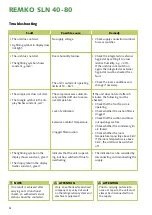
Page 12: ...oes not start The triangle symbol in the dis play flashes constant red The compressor was automati cally switched off due to exces sive temperature Lack of ventilation Excessive ambient temperature Cl...

Page 13: ...pansion valve 5 Dry filter 6 Solenoid valve 7 Fan 8 Non return valve Legend 1 Compressor 2 Evaporator 3 Condenser 4 Thermal expansion valve 5 Dry filter 6 Solenoid valve 7 Fan We reserve the right to...

Page 14: ...External hygrostat Recommended for frequent hu midity variation is the installation of an external hygrostat which is available as an accessory Disconnect the integrated hygro stat at terminals 21 an...

Page 15: ...ly high quality materials are used the majority of which are recyclable Make your contribution towards environmental protection by disposing of your old unit in an environmentally friendly manner Only...

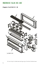
Page 16: ...ve the right to make dimensional and design changes in the interest of technical advances Diagram of unit SLN 40 80 Fig REMKO SLN 80 4 7 8 10 17 18 2 1 9 3 16 13 19 15 14 12 11 6 21 5 22 20 16 REMKO S...

Page 17: ...8 1109169 1109181 9 Condensate tray complete 1109149 1109170 1109182 10 Front panel 1109194 1109195 1109196 11 Evaporator sensor metal 1109160 1109160 1109111 12 Condenser sensor 1109161 1109161 11091...

Page 18: ...ture 17 Date Signature 18 Date Signature 19 Date Signature 20 Date Signature Remarks Model Serial No 1 2 3 4 5 6 7 8 9 10 11 12 13 14 15 16 17 18 19 20 Unit cleaned externally Unit cleaned internally...

Page 19: ...0 750 Power supply V Hz 230 1 50 Max power consumption kW 0 72 1 05 1 65 Max rated power consumption A 2 8 4 3 7 2 Refrigerant R407C Refrigerant quantity kg 0 6 0 95 1 6 Sound pressure level LpA 1m 1...

Page 20: ...ood reliable supplier REMKO a partner that helps solve problems Sales REMKO not only provides an extensive sales network in Germany and abroad but also unusually highly qualified sales experts REMKO s...

Reviews: