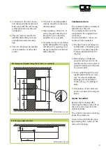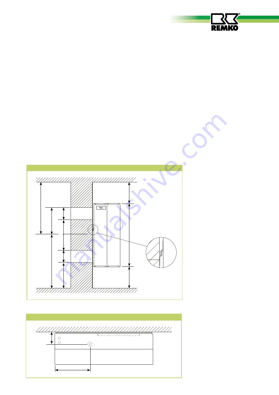
Positioning condensate drain
105
318
Condensate drain
The condensate drain is located at
the bottom of the unit.
The condensate drain must be
connected to the supplied drain
connection.
A solid or flexible ½“ drain con-
nection can be connected.
■
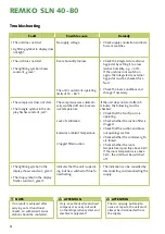
The drain hose must always be
installed with a minimum gradi-
ent of 2% to enable the water
to drain unhindered from the
drip tray.
■
Alternatively, a condensate
pump (accessory) can also be
mounted on the unit in order to
pump the produced condensate
to a raised outlet.
■
For an outlet through the wall,
specific preparations are neces-
sary for correct condensate
drainage prior to installation
of the unit, e.g. the drilling of
holes.
■
The position of the outlet con-
nection is shown in the diagram
below.
Access to control
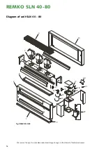
Remove the front plate after
removing the Allen screws. Lift up
the cover and remove from the
unit horizontally.
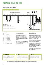
The control is located in a housing
above the compressor.
Access to the control takes place
by removing the 4 screws on the
sides of the housing.
■
Connection to the duct connec-
tion already installed in the wall
takes place with the self-sealing
profile lips located on the unit
connection.
■
The unit must be mounted or
installed horizontally to ensure
unhindered condensate drain-
age.
■
The unit should not be installed
close to radiators or other heat
sources.
■
The room to be dehumidified
must be closed from the ambi-
ent atmosphere.
■
Open windows, doors, etc., as
well as frequent entering and
leaving the room should be
avoided as far as possible.
■
For optimal room air circulation
by the dehumidifier, the supply
and exhaust air openings must
always be kept free of dirt and
other obstacles.
All dimensions in mm
All dimensions in mm
Min. 530
Min. 225
677
Min. 225
130
268
130
600
257
Positioning wall bracket taking the SLN 60 as an example
329
9


