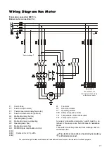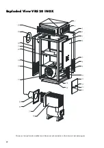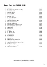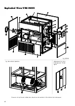
10
Prior to Initial Operation
of the 400 V Series
Fan Motor Operation
Check the drive.
1. Check the rotational direction of the fan.
2. Check the initial tension of the drive belt.
3. Check that the tightening screws of the complete
drive are secure.
Measuring the rated current and/or current consump-
tion.
1. To prevent inaccurate measurements, open the grille
in the air duct or the blow-out cover.
2. Attach all air suction grilles to the unit.
3. Check the available power supply.
4. Measure the current.
◊
Rated current for direct start.
The measured rated current may not exceed the
value on the type plate of the motor. The thermal
overcurrent relay must be adjusted to the rated
current of the drive motor.
◊
Rated current for Y /
∆
start.
The measured rated current may not exceed the
value on the type plate of the motor. Multiply the
rated current of the drive motor by a factor of 0.58
and adjust the thermal overcurrent relay to the
calculated value.
G
Each phase should be measured separately to pre-
vent inaccurate measurements.
Thermal Overcurrent Relay
To check the function of the overcurrent relay or its set
value, remove a fuse. If the unit is functioning and set
properly, the relay should activate after approximately
30 seconds.
Important Information about the Thermal Overcurrent
Relay
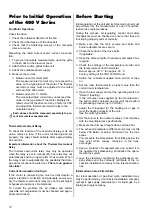
The thermal overcurrent relay may only be operated
when the relay is set to manual (
H
). The relay may not
automatically switch on again after it has cooled. When
the relay is set to automatic (
A
), the possibility that dam-
age will occur cannot be ruled out.
There is no guaran-
tee claim
!
Current Consumption too High
If the motor is consuming too much current despite a
proper electrical connection and adequate power sup-
ply, the thermal overcurrent relay may not be set higher
or bypassed under any circumstances.
To correct the problem, the air intakes and outlets
(possible air compression) must be checked and appro-
priate action taken.
Before Starting
Initial operation of the unit and its forced-air burner must
be performed by the manufacturer or one of its author-
ised service representatives.
During this process, all regulating, control and safety
mechanisms must be checked to ensure that they are
functioning properly and set correctly.
◊
Make sure that the fan’s screws and bolts and
burner attachments are secure.
◊
Check the tension of the drive belts.
If applicable.
◊
Open the blow-out grille if necessary and adjust it as
required.
◊
Check the settings of the temperature monitor and
the temperature control thermostat.
Burner approx. 80 °C; fan approx. 40 °C.
Factory setting at the VRS 20 INOX unit.
◊
Switch the customer-supplied main switch or fuse
on.
◊
Set the room thermostat to a higher value than the
current room temperature.
◊
Open the fuel supply and set the operating switch to
“Heizen” (heating).
If the oil burner was supplied by the manufacturer,
the burner start is delayed as a result of the standard
oil preheating process (up to VRS 60).
◊
Adjust the throughput for the heating oil or gas to
meet the heating capacity of the unit.
See the unit’s type plate.
◊
Set the burner to the optimum values in accordance
with the manufacturer’s specifications.
◊
Measure the chimney draught when cold and hot.
◊
The exhaust temperature difference (
∆
t
) may not fall
below 200 Kelvin or below 160 Kelvin for the Inox
series.
This prevents the temperature from falling below the
dew point which causes corrosion in the heat-
exchanger.
◊
Keep a protocol of measurements and submit it to
the operator for safekeeping. Familiarise the opera-
tor with the system.
◊
Give the statement confirming the authorised com-
pany status and the company certificate of the re-
spective installation company to the relevant authori-
ties.
Information on Gas-Fired Units.
For initial operation of gas-fired units, installation may
only be performed by a contracted installation company
(except in gas supply companies) or, for liquid gas, by a
liquid gas supply company.


