background image

13 

The unit does not start 

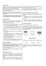
1.   Check the power supply 

2.   Check the fuses in the control box.  

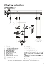
Only for units in the 400 V rotary current series. 

3.   Check the safety temperature limiter. 

If the safety temperature limiter (STB) has been acti-
vated, the reason the unit overheated must be deter-
mined. The following are possible causes: 

The unit could not cool down because the 
power supply was interrupted. Even short inter-
ruptions can activate the STB. 

The temperature of the air being blown out is 
too high because the grilles have not been prop-
erly adjusted. 

The fan was overloaded and the thermal over-
current relay of the 400 V series was activated 
or the thermal contacts in the fan motor of the 
230 V series were activated. 

The V-belt of the fan drive is loose or defective. 

Air intakes and outlets are blocked. 

4.   Check the operating and/or main switch. 

5.  Check the room thermostat setting.  

The room thermostat must be set higher than the 
room temperature. 

6.   Set the operating switch to “Lüften” (fan) or “

II

”.   

If the air supply fan starts now, look for the problem 
in the burner.


Troubleshooting 

 
The unit was subjected to repeating testing during pro-
duction to ensure that it functions properly. 

However, if you still experience functional problems, 
please refer to the list below. 

The burner does not start


Check whether the fuel filter is dirty. 

Check whether the shut-off valve of the fuel filter is 
open. 

Check that there is enough fuel in the fuel container. 

Check whether paraffin has accumulated in the heat-
ing oil.       

This can occur at temperatures below 5 °C.


Check oil lines for damage.    

Leaks can cause air intake.


Use suitable means to ensure that the safety tem-
perature limiter (STB) and the temperature monitor 
(TW) are functioning properly. 

Check the sensors and capillary pipes of the TW and 
STB for damage and ensure that the sensor has 
been properly positioned. 

Check whether the burner malfunction control lamp 
on the oil firing device is illuminated.           

If so, release the relay by pressing the malfunction 
button. The malfunction light goes out and the burner 
tries to start. Keep in mind that some burners have a 
delayed start due to the oil preheating process for 
some units.


G


If, after the start phase, the burner switches off due 
to a malfunction, you may only re-release it after 
waiting 5 min. Additional releases are strictly pro-
hibited as there is a risk of explosion. 

The air supply fan does not start 

Set the operating switch to “Lüften” (fan) or “

II

”.   

The air supply fan should now start. 

Check that the fan and the fan drive are running 
smoothly. 

Check the V-belt on the fan drive. 

Check the electric cord on the fan motor for damage. 

Check whether the capacity of the fan was ex-
ceeded.     

The thermal overcurrent relay (400 V series) or the 
thermal contacts (230 V series) in the fan motor 
have been activated.


Check the operating capacitor of the fan.   

Only for the 230 V series.


Check that the temperature control thermostat (TR) 
is working properly. 

G


Should the unit still not function properly after per-
forming these checks, please contact an author-
ised service centre. 

G


Please carry out an electrical safety test after hav-
ing finished service on the unit.


G


For safety purposes, repair work on the electrical 
components and the burner may only be per-
formed by authorised personnel.


G


An operation/use other than indicated in these in-
structions is prohibited!  
In the case of non-compliance, we assume no li-
ability and our guarantee becomes null and void.


Service and Guarantee


For the guarantee to be valid, the customer must com-
pletely fill out the “guarantee certificate” enclosed with 
all heating units and send it back to REMKO GmbH & 
Co. KG in a timely manner after purchasing of the unit 
and putting it into operation. 

The units have undergone several tests to ensure 
proper functioning at the factory. If there are still mal-
functions that cannot be fixed by the operator using the 
troubleshooting instructions, please contact your dealer 
or contract partner. 

Summary of Contents for VRS 120

Page 1: ...REMKO powerful like a bear REMKO VRS Universal oil gas automatic heaters Edition GB M10 Operation Technology Spare Parts ...

Page 2: ......

Page 3: ...g Diagram 400 V Y Start 20 Wiring Diagram Fan Motor 21 Exploded View VRS 20 INOX 22 Spare Part List VRS 20 INOX 23 Exploded View VRS INOX 24 Spare Part List VRS INOX 25 Exploded View VRS B 26 Spare Part List VRS B 27 Unit Dimensions VRS INOX 28 Unit Dimensions VRS B 28 Read these instructions carefully before setting up operating the unit Our guarantee becomes null and void if the unit is used set...

Page 4: ...for universal fully automatic and smooth operation They are fired directly with heating oil diesel or natural liquid gas The VRS 20 INOX has only been designed for op eration with heating oil or diesel G These units have not been designed for heating private residences or similar spaces G Do not bypass or block safety mechanisms while the unit is in operation Operating Locations of the Units The u...

Page 5: ...p in other rooms if their use requires this e g single heating appliances such as fan heaters and these heating appliances can be safely operated Here the German state building authorities Guidelines for setting up furnaces with a total rated heat output of more than 50 kW in rooms other than heating rooms must be observed The guidelines prohibit erecting furnaces when poten tially dangerous conce...

Page 6: ...ombustion An adequate supply of air for combustion must be en sured by meeting the relevant building requirements Excerpts from the German fire ordinance 1 For furnaces with a total rated heat output of up to 35 kW that are dependent on the air in the room evidence of an adequate air supply for combustion has been provided if the furnaces are set up in a room that has 1 A minimum of one door to th...

Page 7: ...ring capacity Sturdy mounts fixed on the unit are used to attach it In addition the requirements listed in the section Wall As sembly must be observed Outside Setup Units that are set up outside must be adequately pro tected from weather conditions so that they do not have any harmful effects or cause any unreasonable annoy ances during operation The units may only be equipped with armatures and c...

Page 8: ...tion The electrical connection of the units may only be per formed by authorised personnel in accordance with the relevant regulations including any local ones An easily accessible emergency switch must be at tached in the setup room The emergency switch must be protected from unau thorised use Thermostat Connection The room thermostat accessory or day night regulator accessory is connected via sp...

Page 9: ...capacity of the unit and the construction height The dimensions of the exhaust systems must ensure that the exhaust is expelled to the outside regardless of the operating conditions and guarantee that no positive pressure is produced in the rooms These dimensions are based on the cross section and height and to the extent required the heat penetra bility resistance and internal surface The exhaust...

Page 10: ...possible air compression must be checked and appro priate action taken Before Starting Initial operation of the unit and its forced air burner must be performed by the manufacturer or one of its author ised service representatives During this process all regulating control and safety mechanisms must be checked to ensure that they are functioning properly and set correctly Make sure that the fan s ...

Page 11: ...liance with emis sion limits The operator must be informed if defects are found He must then have the unit serviced immediately or its components replaced The following applies Maintenance work on limiting devices self adjusting devices and flame monitoring devices as well as on other safety mechanisms may only be performed by the respective manufacturer or his representatives On the other hand th...

Page 12: ...over 6 and the burner flange Replace them if necessary 7 Service the burner in accordance with the separate operating instructions G Check the burner and all regulating devices to en sure that they are functioning properly and set them to the optimum values Cleaning the Combustion Chamber and the Heat Exchanger of VRS B and VRS INOX Type Units 1 Unplug the unit from the power supply 2 Disassemble ...

Page 13: ...rner malfunction control lamp on the oil firing device is illuminated If so release the relay by pressing the malfunction button The malfunction light goes out and the burner tries to start Keep in mind that some burners have a delayed start due to the oil preheating process for some units G If after the start phase the burner switches off due to a malfunction you may only re release it after wait...

Page 14: ...65 Electrical connection V 230 1 230 1 400 3N 400 3N 400 3N 400 3N 400 3N Frequency Hz 50 50 50 50 50 50 50 Rated current 5 A 2 2 2 6 2 8 3 7 3 7 3 7 5 2 Power consumption 5 kW 0 25 0 25 1 1 1 5 1 5 1 5 2 2 Power consumption 6 kW 0 46 0 46 1 55 1 95 1 95 1 84 2 54 Exhaust gas connection Ø mm 150 150 180 180 200 200 200 Weight 7 kg 150 240 310 360 550 730 820 REMKO VRS 18 16 7 1 050 62 Heating oil ...

Page 15: ... 60 65 Electrical connection 2 V 230 1 230 1 400 3N 400 3N 400 3N 400 3N 400 3N 400 3N 400 3N 400 3N Frequency Hz 50 50 50 50 50 50 50 50 50 50 Rated current 2 5 A 4 5 5 5 2 65 3 6 5 1 6 8 8 8 11 4 8 8 8 8 8 8 8 8 Power consumption 2 5 kW 0 51 0 75 1 1 1 5 2 2 3 0 4 0 5 5 4 0 4 0 4 0 4 0 Power consumption 6 W 210 210 210 450 450 350 350 350 1900 1900 Exhaust gas connection Ø mm 150 150 180 180 180...

Page 16: ...0 12 12 Z 1030 SPZ 2 132 180 72 300 400 50 3 00 6 80 1430 12 12 Z 1145 SPZ 2 125 160 74 410 400 50 3 00 6 80 1430 12 12 Z 1275 SPZ 2 160 180 76 210 80 400 50 3 00 6 80 1430 15 11 Z 750 SPZ 2 118 224 69 150 400 50 4 00 8 80 1435 15 11 Z 835 SPZ 2 106 180 70 270 400 50 5 50 11 40 1450 15 11 Z 945 SPZ 2 132 200 72 370 400 50 5 50 11 40 1450 15 11 Z 1035 SPZ 2 160 224 73 510 400 50 2x 4 0 2x 8 8 1435 ...

Page 17: ...er input KL2 Terminal strip electrical wiring M Fan motor S Operating switch STB Safety temperature limiter TH External thermostat connection TR Temperature control thermostat TW Temperature monitor WS Wieland plug only for factory installed burner An easily accessible emergency switch must be at tached in the setup room but not close to hazardous areas This switch must be protected from damage an...

Page 18: ...serve the right to make modifications in dimensions and construction in the interests of technical progress C Capacitor KB REMKO Triple Combination Control KL Terminal strip in the control box M Fan motor RT Thermostat plug S Operating switch SK Control box STB Safety temperature limiter TR Temperature control thermostat TW Temperature monitor WS Wieland plug Only for factory installed burner Wiel...

Page 19: ...unction lamp fan H2 Operating lamp fan H3 Operating lamp burner H4 Malfunction lamp burner K1 Fan contactor KB REMKO triple combination control M Fan motor RT1 Room thermostat day accessory RT2 Room thermostat night accessory S1 Operating switch STB Safety temperature limiter TR Temperature control thermostat TW Temperature monitor X1 Terminal strip 1 in the control box X2 Terminal strip 2 in the ...

Page 20: ...t to make modifications in dimensions and construction in the interests of technical progress red opt Running hour meter red white white Heat Fan Off red Terminal strips in the control box numbered burner cable Fan motor Supply line During the thermostat connection Remove bridge Burner plug ...

Page 21: ...l We reserve the right to make modifications in dimensions and construction in the interests of technical progress F1 Control fuse F2 Fuse block fan motor F3 Thermal overcurrent relay fan motor F4 Fuse block burner motor optional H2 Malfunction lamp burner H3 Operating lamp burner H4 Malfunction lamp overheating H5 Operating lamp fan H6 Malfunction lamp fan KB REMKO triple combination control K1M ...

Page 22: ...22 Exploded View VRS 20 INOX We reserve the right to make modifications in dimensions and construction in the interests of technical progress ...

Page 23: ...r malfunction 1105513 13 Control lamp GREEN operation display 1105514 14 Operating switch 1101188 15 Unit frame cpl 1103148 16 Base plate 1103149 17 Air supply fan cpl 1108606 18 Air intake grille back 1103150 19 Intermediate plate 1130151 20 Fan regulator TR 1101683 21 Insulation back 1103152 22 Lining plate back 1103153 23 Rosette for exhaust gas connection 1103285 24 Blow out grille side 109534...

Page 24: ...Replacement for No 6 for design size 130 and higher Fig Fan with belt operation Exploded View VRS INOX We reserve the right to make modifications in dimensions and construction in the interests of technical progress ...

Page 25: ... 1103255 1103255 1103255 1103255 15 Flue gas brake 1102953 1102954 1102955 1102956 1102967 1102957 1102957 16 Fan cpl 230 V 1 1108423 1108602 17 Slotted plate suction 1103260 1103261 1103261 1103262 1103268 1103269 1103269 18 Seal for inspection cover 1103273 1103273 1103274 1103274 1103275 1103275 1103275 19 Inspection cover side 1103278 1103278 1103279 1103279 1103280 1103280 1103280 20 Seal for...

Page 26: ...5 a b 20 26 13 27 30 31 32 33 34 28 18 19 24 23 21 22 17 16 2 3 4 1 29 35 Exploded View VRS B Fig VRS 80 upright model We reserve the right to make modifications in dimensions and construction in the interests of technical progress ...

Page 27: ...90 1104291 1104291 16 Seal 1104292 1104292 1104292 1104292 1104292 1104293 1104293 1103234 1103234 1103234 17 Burner plate 1104294 1104294 1104294 1104294 1104294 1104295 1104295 1103237 1103237 1103237 18 Lining plate front middle 1104297 1104298 1104298 1104299 1104299 1104300 1104300 1104301 1104302 1104302 19 Insulation front middle 1104304 1104305 1104305 1104306 1104306 1104307 1104307 20 Bl...

Page 28: ...C 1285 1500 1700 1700 1800 2095 2260 2260 C1 1470 1570 1870 2070 2270 D 580 955 1052 1052 1100 1230 1330 1330 E 890 815 900 900 907 1075 1160 1160 F 35 35 35 35 35 35 35 35 G 262 335 435 435 485 540 635 635 R 150 150 150 180 180 200 200 200 Standing Unit Unit on its side C D B A E ø R C1 B G F A We reserve the right to make modifications in dimensions and construction in the interests of technical...

Page 29: ...E 545 775 775 928 928 1234 1234 1377 1530 1530 F 1073 1210 1210 1325 1583 1092 1092 1123 1257 1257 G 515 515 515 515 622 622 622 605 765 765 ø P 120 130 130 145 142 190 190 215 240 240 R ø 150 150 180 180 180 200 250 250 300 300 S 982 976 976 1078 1308 1392 1392 1520 1736 1736 Weight kg 190 260 305 365 450 680 735 930 1055 1240 dependent on the respective oil or gas forced air burner Standing Unit...

Page 30: ... damage Maintenance burner Test run Model Model No Burner Burner No Maintenance work may only be performed by authorised personnel settings must comply with legal specifications A corresponding test log must be kept Remarks 1 Date 2 Date 3 Date 4 Date 5 Date Signature Signature Signature Signature Signature 6 Date 7 Date 8 Date 9 Date 10 Date Signature Signature Signature Signature Signature 11 Da...

Page 31: ......

Page 32: ...REMKO GmbH Co KG Klima und Wärmetechnik D 32791 Lage Im Seelenkamp 12 D 32777 Lage PO Box 1827 Phone 49 5232 606 0 Fax 49 5232 606260 ...

Reviews: