

25
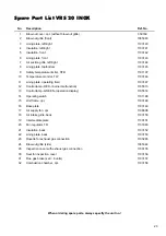
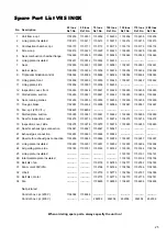
No.
Description
25 Inox
Ref. No.
50 Inox
Ref. No.
75 Inox
Ref. No.
100 Inox
Ref. No.
130 Inox
Ref. No.
170 Inox
Ref. No.
200 Inox
Ref. No.
1
Unit frame, cpl.
1103200
1103201 1103202
1103203
1103204
1103205 1103205
2
Lining plate, insulated
1103210
1103211 1103212
1103213
1103214
1103215 1103215
3
Combustion chamber, cpl.
1103170
1103171 1103172
1103173
1103174
1103175 1103176
4
Screw cap
1103219
1103220 1103220
1103220
1103220
1103220 1103220
5
Seal, combustion chamber flange.
1102948
1102949 1102949
1102949
1102949
1102949 1102949
6
Lining plate, insulated
1103231
1103232 1103232
1103233
-----------
-----------
-----------
7
Seal
1102950
1102951 1102951
1102951
1102951
1102951 1102951
8
Burner plate
1103235
1103236 1103236
1103236
1103236
1103236 1103236
9
Triple combination control
1108386
1108386 1108386
1108386
1108386
1108386 1108386
10
Lining plate, front
1103238
1103239 1103239
1103240
1103241
1103242 1103242
11
Lining plate, side
1103256
1103257 1103258
1103259
-----------
-----------
-----------
12
Inspection cover, front
1103245
1103246 1103247
1103248
1103249
1103250 1103250
13
Slotted plate, suction
1103260
1103261 1103261
1103262
1103263
1103264 1103264
14
Seal, running metres
1103255
1103255 1103255
1103255
1103255
1103255 1103255
15
Flue gas brake
1102953
1102954 1102955
1102956
1102967
1102957 1102957
16
Fan, cpl. (230 V/1~)
1108423
1108602
-----------
-----------
-----------
-----------
-----------
17
Slotted plate, suction
1103260
1103261 1103261
1103262
1103268
1103269 1103269
18
Seal for inspection cover
1103273
1103273 1103274
1103274
1103275
1103275 1103275
19
Inspection cover, side
1103278
1103278 1103279
1103279
1103280
1103280 1103280
20
Seal for exhaust gas connection
1102947
1102947 1102947
1102947
-----------
-----------
-----------
21
Exhaust gas connection
1103283
1103283 1103284
1103284
-----------
-----------
-----------
22
Rosette for exhaust gas connection
1103285
1103285 1103286
1103286
1103287
1103287 1103287
23
Lining plate, insulated
1103290
1103291 1103291
1103292
1103293
1103294 1103294
24
Air guiding plate, side
1103180
1103181 1103182
1103182
1103183
1103184 1103184
25
Lining plate, insulated
-----------
-----------
-----------
-----------
1103190
1103191 1103191
26
Intermediate plate, insulated
-----------
-----------
-----------
-----------
1103195
1103196 1103196
30
Belt disc, fan
-----------
-----------
1102776
1102780
1102777
1102782 1102783
31
Fan motor 400V/3N~
-----------
-----------
1102768
1102766
1102766
1102766 1102769
32
V-belt
-----------
-----------
1102779
1102773
1102786
1102787 1102788
33
Belt disc, motor
-----------
-----------
1102770
1102770
1102770
1102770 1102781
34
Fan
-----------
-----------
1108600
1108550
1108601
1108604 1108605
Not pictured
Control box, cpl. (230 V)
1108388
1108388
-----------
-----------
-----------
-----------
-----------
Control box, cpl. (400 V)
-----------
-----------
292306
292306
292306
292306
292306
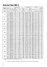
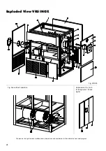
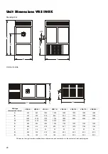
Spare Part List VRS INOX
When ordering spare parts, always specify the unit no.!


