

27
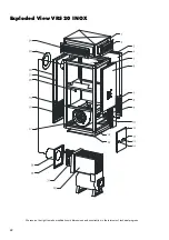
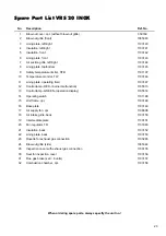
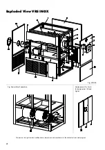
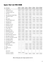
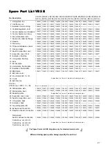
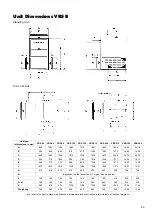
Spare Part List VRS B
No.
Description
VRS 40
Ref. No.
VRS 60
Ref. No.
VRS 80
Ref. No.
VRS 120
Ref. No.
VRS 150
Ref. No.
VRS 210
Ref. No.
VRS 250
Ref. No.
VRS 310
Ref. No.
VRS 380
Ref. No.
VRS 450
Ref. No.
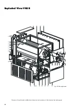
1 Lining plate, top
1104201 1104202 1104202 1104203 1104204 1104205 1104205 1104206 1104207 1104208
2 Unit frame, cpl.
1104209 1104210 1104211 1104212 1104213 1104214 1104214 1104215 1104216 1104217
3 Insulation for side lining
1104218 1104219 1104220 1104221 1104222 1104223 1104223 ———— ———— ————
4 Verkleidungsblech, seitl.
1104227 1104228 1104229 1104230 1104231 1104232 1104232 1104233 1104234 1104235
5 Comb. chamber cpl. (Standard)
1104237 1104238 1104239 1104240 1104241 1104242 1104243 1104244 1104245 1104246
5 Comb. chamber cpl. (Inox)
1104248 1104249 1104250 1104251 1104252 1104253 1104254 1104255 1104256 1104257
6 Air guiding plate, right
1104258 1104259 1104260 1104261 1104262 1104263 1104263 1104264 1104265 1104266
7 Seal comb. chamber flange
1104267 1104267 1104267 1104267 1104267 1104268 1104268 1104375 1104375 1104375
8 Rosette
1104269 1104269 1104269 1104269 1104269 1104269 1104269 1104269 1104269 1104269
9 Screw cap
1103219 1103219 1103219 1103219 1103219 1103219 1103219 1103219 1103219 1103219
10
Triple combination control
1102572 1102572 1102572 1102572 1102572 1102572 1102572 1102572 1102572 1102572
11 Flue gas brake
1102953 1102954 1102955 1102955 1102955 1102957 1102957 1102958 1102958 1102959
12 Seal for inspection cover
1103255 1103255 1103255 1103255 1103255 1103255 1103255 1103255 1103255 1103255
13 Inspection cover, front
1104271 1104272 1104272 1104273 1104273 1104274 1104274 1104275 1104276 1104277
14 Insulation, front/top
1104279 1104280 1104280 1104281 1104281 1104282 1104282 ———— ———— ————
15 Lining plate, front/top
1104286 1104287 1104287 1104288 1104288 1104289 1104289 1104290 1104291 1104291
16 Seal
1104292 1104292 1104292 1104292 1104292 1104293 1104293 1103234 1103234 1103234
17 Burner plate
1104294 1104294 1104294 1104294 1104294 1104295 1104295 1103237 1103237 1103237
18 Lining plate, front/middle
1104297 1104298 1104298 1104299 1104299 1104300 1104300 1104301 1104302 1104302
19 Insulation, front/middle
1104304 1104305 1104305 1104306 1104306 1104307 1104307 ———— ———— ————
20 Blind plate
1104311 1104312 1104312 1104313 1104314 1104315 1104315 1104316 1104317 1104317
21 Belt disc, motor
dependent on the unit model and compression
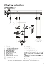
22 Fan motor 400V / 3~/ N
23 V-belt
24 Belt disc, fan
25a Fan
25b Fan, cpl. (230 V / 1~ / N)
dep. on compres.
----------- ----------- ----------- ----------- ----------- ----------- ----------- -----------
26 Slotted plate, side
1104318 1104319 1104320 1104320 1104321 1104322 1104322 1104322 1104323 1104324
27 Slotted plate, back
1104326 1104327 1104327 1104328 1104329 1104330 1104330 1104331 1104323 1104323
28 Assembly plate
dependent on the unit model and compression
29 Inspection cover, side
1104333 1104333 1104333 1104333 1104333 1104334 1104334 1104335 1104336 1104336
30 Seal for inspection cover
1103255 1103255 1103255 1103255 1103255 1103255 1103255 1103255 1103255 1103255
31 Lining plate, back
1104338 1104339 1104340 1104341 1104341 1104342 1104343 1104344 1104345 1104345
32 Insulation, back
1104347 1104348 1104349 1104350 1104350 1104351 1104352 ———— ———— ————
33 Air guiding plate, left
1104356 1104357 1104358 1104359 1104360 1104361 1104361 1104362 1104363 1104364
34 Exhaust gas connection
1104366 1104367 1104368 1104369 1104369 1104370 1104371 1104372 1104373 1104373
35 Rosette, exhaust connection
1103285 1103285 1103286 1103286 1103286 1103287 1103288 1103288 1103289 1103289
Not pictured
Seal for exhaust connection
1103255 1103255 1103255 1103255 1103255 1103255 1103255 1103255 1103255 1103255
Control box, cpl. (230 V)
Control box, cpl. (400 V)
Control box, cpl. ( Y
∆
)
dependent on the unit model and compression
When ordering spare parts, always specify the unit no.!
G
The Spare Parts List VRS B applies only for standard model units.
G


