


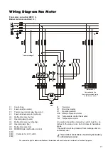

9
G
Make sure to maintain a safe distance to flamma-
ble materials!
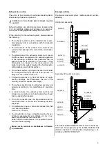
Examples of Use
Double-sided exhaust system / stainless-steel / outside
assembly.
Assembly of the unit on its side
AS-500-E
AS-ÜGI-D
AS-ME-D
AS-1000-D
AS-T90-D
AS-RT-D
AS-GI-D
AS-WK-D
AS-RB90-E
Wall
console
The double-walled, REMKO stainless steel exhaust sys-
tems have been approved by the
Institut für Bautechnik
(German Institute for Construction Engineering) in ac-
cordance with DIN 18160 Part 1.
Upright unit assembly
AS-1000-E
AS-ÜGI-D
AS-ME-D
AS-1000-D
AS-T90°-D
AS-RT-D
AS-GI-D
AS-WK-D
Exhaust systems are structural systems located either
in or on buildings whose sole purpose is to expel ex-
haust from heating appliances safely above the roof.
G
Installation of an exhaust system always requires
a permit.
Exhaust Connection
The unit is to be connected to suitable exhaust systems
whose design has been approved.
When planning for the exhaust system, please observe
the following:
◊
The exhaust system must be installed and assem-
bled properly and in accordance with the relevant
regulations.
◊
The dimensions of the exhaust lines must be ad-
justed to the capacity of the unit and the construction
height.
◊
The dimensions of the exhaust systems must ensure
that the exhaust is expelled to the outside regardless
of the operating conditions and guarantee that no
positive pressure is produced in the rooms. These
dimensions are based on the cross-section and
height, and to the extent required, the heat penetra-
bility resistance and internal surface.
◊
The exhaust system openings must stick out at least
40 cm beyond the top of the roof or be at least 1 m
away from the surface of the roof.
◊
If impact pressures, e.g. from fall winds or neigh-
bouring buildings, are anticipated, the top of the
chimney should be shaped accordingly.
◊
The exhaust system must be attached securely and
properly according to the manufacturer’s specifica-
tions.
◊
In roof structures, the exhaust system must be led
through a pipe casing or a chute to allow the exhaust
line to expand when heated.
◊
The unit connection must be impermeable and se-
cured with rivets or screws from becoming acciden-
tally loose.
◊
It is preferable to have a horizontal exhaust line that
is as short as possible.
Incline 2 % = 2 cm/m.
◊
You should plan to have a closable opening for per-
forming measurements at a distance of 2 x
∅
ex-
haust pipe behind the unit connection.
Under certain circumstances, it is possible to meas-
ure the exhaust opening.


