16
Oil Burner Assembly
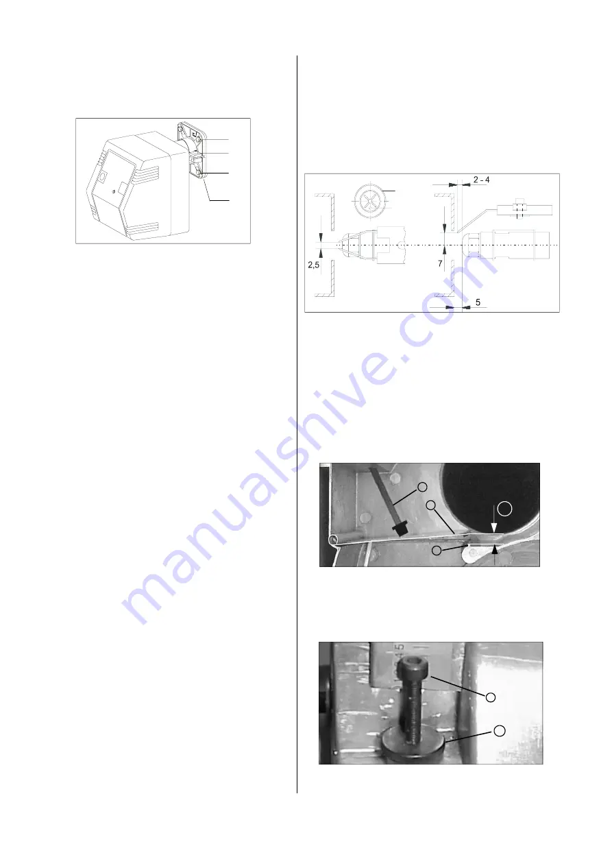
The supplied burner flange 1 which is attached with 4
screws is used to mount the oil burner.
Initial Operation
Initial operation of the oil burner may only be per-
formed by authorised personnel
!
4
3
2
1
Setting ignition electrode and stabilising disk
Adjusting the Air flap
Adjust the air flap with the adjustment screw 7 in such a
way that the distance A between air flap 8 and stop posi-
tion 9 is approx. 8 mm.
Proceed as follows to set the required distance:
1. Loosen the knurled screw 10 and rotate the adjust-
ment screw 7 accordingly.
Rotate right
distance A becomes smaller
Rotate left
distance A becomes greater
A
7
8
9
10
7
1. Hold the assembly base plate horizontally.
2. Slide the right mount laterally into the suspension
and hang the left side into the top of the lug.
All measurements are
approx. values in mm
Electrical Connection
The electrical connection to the warm air generator is
made via a standardised 7-pole plug connection whose
socket is attached to the burner.
1. Make sure to observe the “OBEN“ (top) label on the
burner.
2. Tighten the upper screws 2 firmly.
3. Turn the lower screws 4 manually but not so that
they are completely tight initially.
The sliding flange still has to be tightened
.
4. Push the flame pipe into the burner chamber until it
clicks into place.
5. Connect the flame pipe to the flange 3 by slightly lifting
the burner (3° incline).
To do this, use a 6 mm Allen wrench.
6. Finally, tighten the lower screws 4.
Oil Connection
The supplied oil lines are connected to the oil pump and
fastened into place with the clamp. The shut-off and fil-
ter fittings have to be arranged in such a way that the
hoses can be properly guided. The hoses may not be
bent!
Prior to operation
After removing the burner cover and loosening the 4
housing screws, the assembly base plate is removed
from the housing and suspended to the side.
The most important functional components for service
and maintenance in accordance with respective re-
quirements are immediately freely accessible.
For maintenance as well as installation and nozzle re-
placement, the assembly base plate can also be sus-
pended horizontally.
1. Attach the the stabilising disk 5 in such a way that
the inspection window 6 of the photo cell is vertical
and at the bottom.
The optimum setting must be adjusted to the local
conditions and the exhaust-side conditions.
2. After a setting the distance, retighten the adjustment
screw with the knurled nut 10.
5
6


