N1-HV/AC Series
User Manual
16
N1-HV/AC Series
User Manual
17
5.7 Electrical Wiring Connection
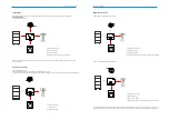
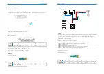
The Overview of the connection terminals of inverter please refer to Figure 3-2, and the wiring connections please refer to
Figure 3-1 the PV energy storage system wiring diagram in chapter 3.1.
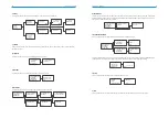
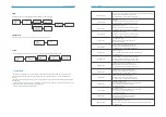
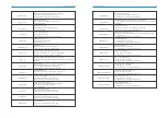
System Connection Diagrams
Note: This diagram is an example for Australian
,
South Africa and New Zealand grid system where neutral line can't be switched.
5.7.1 PV Wiring Connection(Only for N1-HV series inverter)
Before connecting PV strings to N1-HV series hybrid inverter, please make sure requirements are followed as below :
·
The total short- circuit current of PV string must not exceed inverter’s max DC current .
·
Make sure open circuit voltage of PV string is less than 600V.
·
PV strings could not connect to earth/grounding conductor.
·
Use the right PV plugs in the accessory box, BAT plugs are similar with PV plugs, please confirm before use it.
1.Turn off the DC switch.
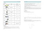
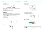
2.Prepare 2.5-4mm2 PV cable and PV plugs as below.
3.Strip 7mm of the conductor with stripping plier. Use a suitable stripping tool for this (e.g. "PV-AZM-410 ")
4.Insert striped cable into pin contact and ensure all conductor strands are captured in the pin contact.
5.Crimp pin contact by using a crimping pliers(PV-CZM-22100). Put the pin contact with striped cable into the corresponding
crimping pliers and crimp the contact.
6.Insert pin contact through the cable nut to assemble into back of the male or female plug. When you feel or heard a ‘click’
the pin contact assembly is seated correctly.
·
PV string connection
·
AC output connection
·
Battery connection
·
Battery power connection
·
Battery communication connection
·
EPS connection
·
Earth connection
·
Communication connection
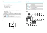
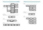
The main steps to connect the N1-HV/AC series system
Connection Steps:
PV Panels
Grid
Meter
Note: This diagram is an example for grid system without special requirement on electrical wiring connection.
PV Panels
Grid
Meter

